| Prev |
heroicrelics.org U.S. Space & Rocket Center Site Index Skylab Mockup Gallery |
Next |
dsc18228.jpg
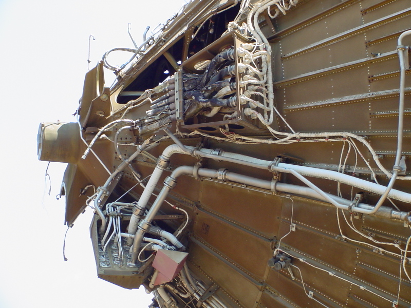
Detail of the aft end of the thrust structure.
Picture 2 of 2.
At left center is the stage's J-2 engine gimbal fitting (where the engine's gimbal block would attach to the thrust structure).
On either side of the gimbal fitting (at the 2:00 and 8:00 positions) are the fittings for stage's LOX and LH2feed lines. At upper center is the opening in the thrust structure through which the liquid hydrogen feed line would emerge.
The panel below and aft of the gimbal fitting is the stage's "customer connect fluid system," the pneumatic interface to the engine.
Also note, at upper center, is the "customer connect electrical system," the electrical interface to the stage. The cables from the engine, at left, appear to have been cut off, rather than disconnected in an orderly fashion. This is similar to the way the engine's propellant inlet ducts were apparently cut off rather than disconnected.
| Time picture taken | Sat Jul 15 11:09:29 2006 |
| Location picture taken |
Rocket Park U.S. Space & Rocket Center Huntsville, AL |
| Prev |
heroicrelics.org U.S. Space & Rocket Center Site Index Skylab Mockup Gallery |
Next |