| Prev |
heroicrelics.org U.S. Space & Rocket Center Site Index Mercury-Redstone Tail Unit Interior Gallery |
Next |
dsc94182.jpg
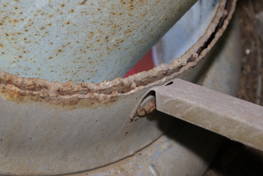
Detail of the cut-off A-7 thrust chamber.
Picture 2 of 2.
Fuel is discharged from the turbopump, flows through the fuel line, passes through the main fuel valve, and enters the fuel inlet manifold. From there, it passes between the two walls which comprise the thrust chamber, providing regenerative cooling for the inner thrust chamber wall as the fuel flows to the injector at the forward end of the engine.
Notice the wires welded to the thrust chamber wall; these are presumably to provide passages for the flow of fuel and to ensure that the two walls of the thrust chamber do not come in contact with each other. These wires appear to be arranged coaxially; in some thrust chambers (e.g., the LR-101), such wires are arranged in a coil, producing a spiral fuel flow to adjust heat flow from the thrust chamber wall to the fuel.
| Time picture taken | Tue Sep 10 14:02:32 2013 |
| Location picture taken |
Rocket Park U.S. Space & Rocket Center Huntsville, AL |
| Prev |
heroicrelics.org U.S. Space & Rocket Center Site Index Mercury-Redstone Tail Unit Interior Gallery |
Next |