| Prev |
heroicrelics.org U.S. Space & Rocket Center Site Index Apollo Fuel Cell (Space Hall) Gallery |
Next |
dsc03463.jpg
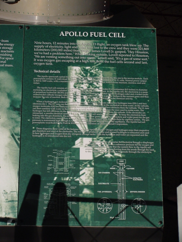
One of the signs which accompanied the fuel cell.
It read
Apollo Fuel Cell
Nine hours, 12 minutes into the Apollo 13 flight, an oxygen tank blew up. The supply of electricity, light, and water was lost to the crew and they were 321,869 kilometers (200,000 miles) from Earth. James Lovell Jr. gasped, "Hey Houston, we've had a problem here." While looking outside, Lovell reported to Houston, "We are venting something out into space." Lovell said, "It's a gas of some sort." It was oxygen gas escaping at a high rate from the fuel cells' second and last, oxygen tank.
Technical Details
The Apollo spacecraft carried three hydrogen-oxygen fuel cell powerplants like this one in the Service Module. Each powerplant contains 31 individual fuel cells connected in series and operated at 27 to 31 volts. Normal power output is 563 to 1,420 watts, with a maximum of 2,300 watts. Primary construction materials are titanium, stainless steel, and nickel.
The Apollo fuel cell consists of two porous metal plate-shaped electrodes 21.6 centimeters (8.5 inches) in diameter enclosing an electrolyte; a solution which can conduct an electrical current. In the Apollo cell, the electrolyte is a paste of potassium hydroxide (KOH) and water (H2O); the electrodes are a nickel anode (hydrogen side) and a nickel-oxide coated nickel cathode (oxygen side). The electrodes are porous to expose a greater surface to the reactant gases and thus increase the rate of reaction. Both the electrolyte and the electrodes participate in the chemical activity.
When a hydrogen gas molecule contacts the anode, the nickel catalyzes it into two hydrogen ions (2H+) and two electrons (2e-). The H+ ions can then combine with hydroxyl ions (OH-) in the electrolyte to form water. At the cathode, oxygen molecules (O2) are catalyzed to form two oxygen ions (2O-), taking two electrons from the cathode. The O- ions can then combine with water in the electrolyte to form hydroxyl ions to replace the ones used to make water. The hydrogen has left electrons on the anode and the oxygen has taken electrons from the cathode. If the electrodes are connected, a usable electrical current will then flow and the fuel cell reaction can continue. To keep the electrolyte from leaking into the gas chambers, the electrodes have very narrow pores next to the electrolyte and wider pores for the gas to enter. The electrolyte cannot flow through the narrow pores; it must seep through them by capillary action. The gas pressure is maintained high enough to keep the electrolyte from seeping out of the capillaries. The Apollo fuel cell powerplants were built by the Pratt & Whitney Aircraft Division of United Aircraft Corporation.
These diagrams show some of the features of a single fuel cell. Oxygen and hydrogen enter their respective gas chambers and react at the electrodes. The mixture of produced water and unused hydrogen is exhausted and used to heat hydrogen and oxygen from the cryogenic storage tanks. Then the hydrogen and water are separated and the hydrogen is re-introduced into the cell.
Nitrogen is used to pressurize the electrolyte through a diaphragm arrangement and to provide a reference pressure for the oxygen and hydrogen regulators. Note that the current flow in the Apollo cell consists of negative charges flowing from the anode through the load to the cathode, and then back to the anode through the electrolyte.
| Time picture taken | Fri Jun 20 14:48:28 2003 |
| Location picture taken |
Space Hall "Old" Museum U.S. Space & Rocket Center Huntsville, AL |
| Prev |
heroicrelics.org U.S. Space & Rocket Center Site Index Apollo Fuel Cell (Space Hall) Gallery |
Next |