| Prev |
heroicrelics.org Science Museum Oklahoma Site Index J-2 Engine Gallery |
Next |
dsc46211.jpg
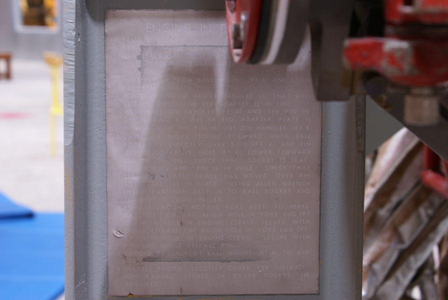
One of the decals on an upright member on the forward end of the dolly.
This is the top label and, although badly faded, appears to read
ENGINE INSTALLATION
- Remove decking from top of handler.
- Remove engine cover and cover sling from handler base. Stow handler dust cover. Replace decking (corrugated side up for shipping only).
- Remove cap from ball mount (Pt. A) and stow between gussets.
- Position engine above handler so that ball socket on engine red adapter is in line with ball on handler (Pt. A) and the pin in the bearing at engine red adapter plate is in line with the pin mount on handler (Pt. B).
- Carefully move engine forward until ball socket is directly over ball (Pt. A) and pin is in slot above hole (Pt. B). Lower forward end of engine. Check that socket is seated on ball and pin is in hole. Check that spring actuated slider has moved over pin to secure it in place. Using Allen wrench insert fastener assy in to ball socket and torque to 20-40 in lbs.
- For aft mount rotate yoke assy to vertical position and align hole in yoke lug (Pt. C1) with hole in engine clevis. Secure with quick release pin. Align hole in yoke lug (Pt. C2) with hole in engine clevis. Secure with pin and quick release pin.
- Torque fastner[sic] at ball mount (Pt. A) to 400-500 in lbs. and safety wire.
- Install engine security cover per instruction manual. Stored in cover pocket. (If required.).
| Time picture taken | Wed Jul 30 15:40:02 2008 |
| Location picture taken |
Open-Air Exhibit Gallery Science Museum Oklahoma (formerly the Omniplex) Oklahoma City, OK |
| Prev |
heroicrelics.org Science Museum Oklahoma Site Index J-2 Engine Gallery |
Next |