| Prev |
heroicrelics.org National Air and Space Museum Site Index Lunar Module 2 (LM-2) Gallery |
Next |
dsc32646.jpg
Ground-level side detail of part of the front (+Z) face of LM-2.
Near the top can be seen the bottom part of the rendezvous radar antenna. The spiral construction of the in-flight S-Band antenna is clearly visible. Below that is the tracking light.
Details of the attachment points for the EVA handrail are visible, and this shot also shows the handle running along the top of the LM. This handrail is used in the event that the LM or CM cannot open their hatches after docking; in such a contingency, the astronauts would exit the LM through the ingress/egress hatch and use the handrail to traverse to the top of the LM, where they would then use the EVA handles on the CM to make their way to the CM's hatch.
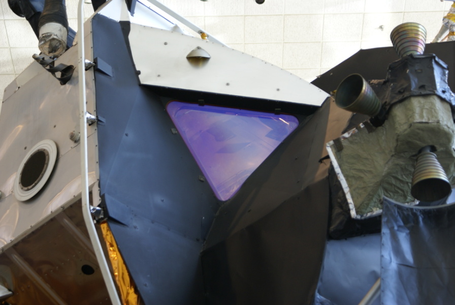
At center is the commander's observation window and at right is part of one of the RCS thruster quads.
I'm uncertain as to the heritage of this observation window: On manned Lunar Modules, the commander's window had a "landing point designator", a series of markings on the window (as shown on LM-9 at Kennedy Space Center) which were used in conjunction with the guidance computer to assist the commander in choosing the exact landing point. For additional information, see the "Descent Planning" section of the Apollo Experience Report: Mission Planning for Lunar Module Descent and Ascent (see page 3 of the document, which is page 11 of the PDF; a diagram depicting the LM forward window appears on page 6/page 14).
However, as LM-2 was configured for unmanned use, it may have lacked the LPD.
| Time picture taken | Fri Jun 22 10:44:40 2007 |
| Location picture taken |
Lunar Exploration Vehicles Gallery National Air and Space Museum Washington, DC |
| Prev |
heroicrelics.org National Air and Space Museum Site Index Lunar Module 2 (LM-2) Gallery |
Next |