| Prev |
heroicrelics.org National Air & Space Museum Site Index F-1 Engine Gallery |
Next |
dsc78415.jpg
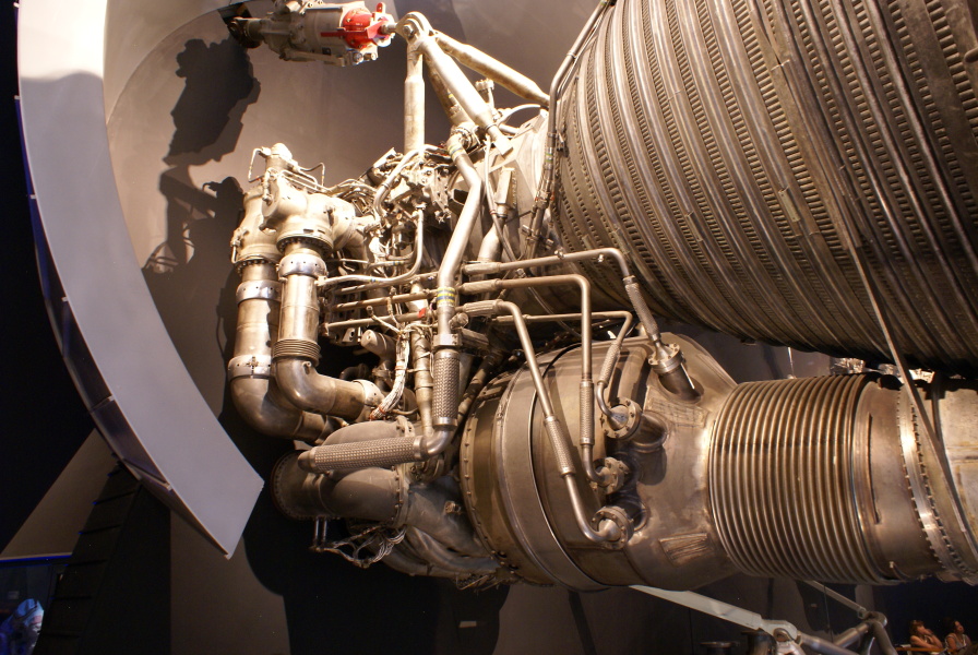
Overall view of the forward end of the engine.
Barely visible at the top is the gimbal actuator.
The LOX (back) and fuel high-pressure ducts are visible at left. Under them is one of the fuel inlet elbows. Note the lack of interface panel around forward of the fuel inlet.
At the bottom of the photo is the heat exchanger (with the four tubes leading to the forward end of the engine). Helium (from storage tanks in the S-IC's LOX tank) and liquid oxygen (from the engine's supply) are routed through the heat exchanger to expand the gasses, which are then sent to the S-IC's fuel and LOX tanks to pressurize them.
This is an early production engine, and the arrangement of the tubes entering and leaving the heat exchanger differs somewhat from later engines. Based on the later version of the heat exchanger, I would expect the tubes to be, from top to bottom:
- The helium inlet
- The oxidizer inlet
- The helium outlet
- The oxidizer outlet
Without the tabs and studs to support the thermal insulation, the side of the thrust chamber seems strangely smooth (as an early engine, this engine was delivered without any provision for thermal insulation).

| Time picture taken | Sat Jun 25 11:47:40 2011 |
| Location picture taken | Apollo to the Moon Gallery National Air & Space Museum Washington, DC |
| Prev | F-1 Engine Gallery | Next |