
Titan I Second Stage Engine (LR-91)
The Titan missiles used the LR-91 as its second stage engine.
The LR-91 was powered by liquid oxygen (LOX) and RP-1 in the Titan I. In the Titan II, it was powered by Aerozine-50 (a 50-50 blend of unsymmetrical dimethylhydrazine [UDMH] and hydrazine) and nitrogen tetroxide (N2O4). I've found relatively little documentation for the UDMH/N2O4 version of the engine, or the specific changes which were necessary to convert to the new propellants. Additionally, I've not seen anything to indicate that the Titan II used the second stage's vernier engine system.
Click image for a 2145x2829 pixel version of this image in a new window.
Taken from p. 1-100 (p. 7 in Section
7 [direct link to 20.3 meg PDF]; of the T.O.
21M-HGM25A-1.1, Technical Manual - Operational and Organization Maintenance
USAF Model HGM-25A Missile Weapon System Operation)
Scan by Titan I Epitaph
Extraction and clean-up by heroicrelics.org.
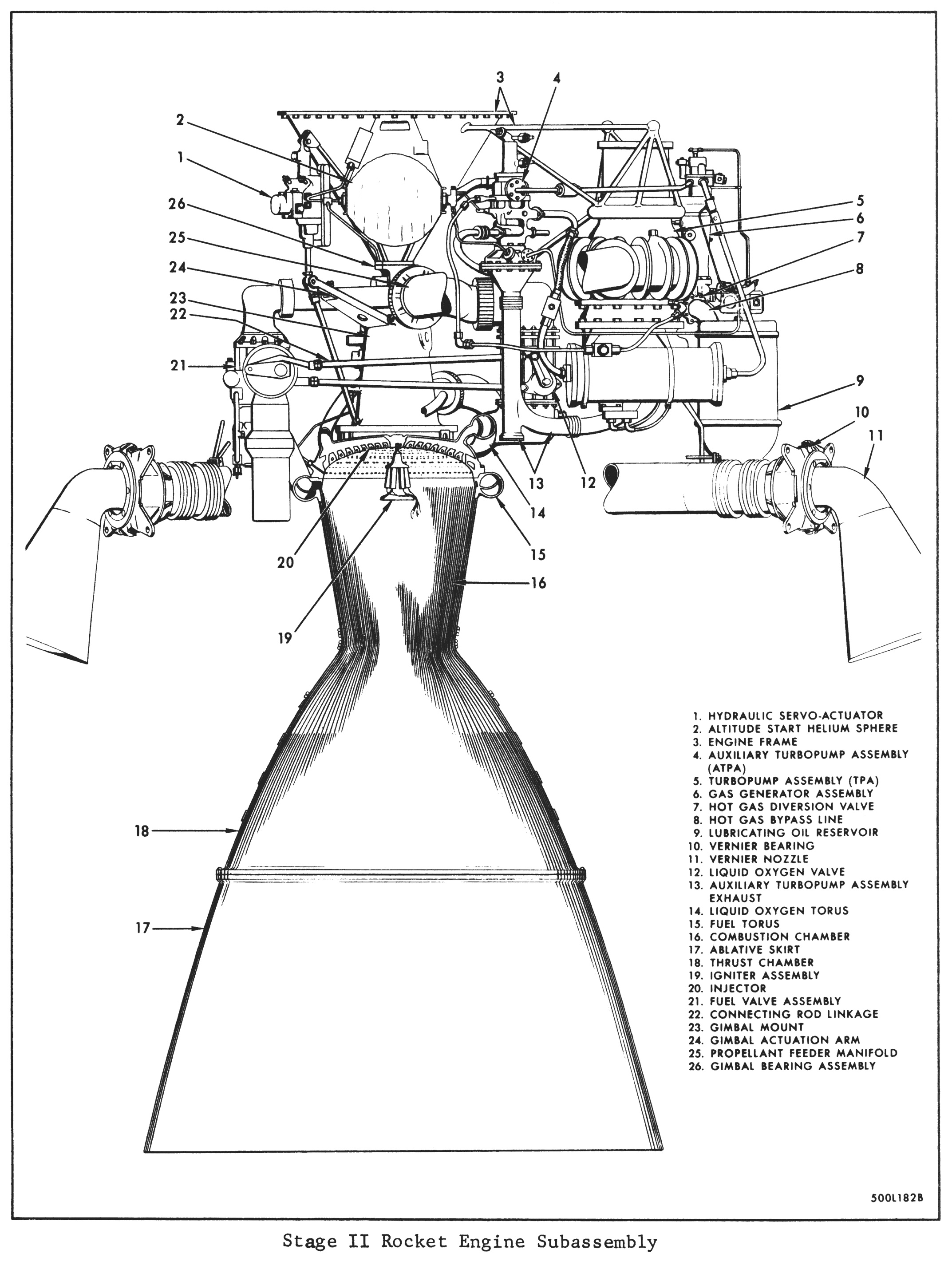
Click image for a 2145x2850 pixel version of this image in a new window.
Taken from p. 1-104 (p. 11 in Section
7 [direct link to 20.3 meg PDF]; of the T.O.
21M-HGM25A-1.1, Technical Manual - Operational and Organization Maintenance
USAF Model HGM-25A Missile Weapon System Operation)
Scan by Titan I Epitaph
Extraction and clean-up by heroicrelics.org.
- 1. Hydraulic Servo-Actuator
- 2. Altitude Start Helium Sphere
- 3. Engine Frame
- 4. Auxiliary Turbopump Assembly (ATPA)
- 5. Turbopump Assembly (TPA)
- 6. Gas Generator Assembly
- 7. Hot Gas Diversion Valve
- 8. Hot Gas Bypass Line
- 9. Lubricating Oil Reservoir
- 10. Vernier Bearing
- 11. Vernier Nozzle
- 12. Liquid Oxygen Valve
- 13. Auxiliary Turbopump Assembly Exhaust
- 14. Liquid Oxygen Torus
- 15. Fuel Torus
- 16. Combustion Chamber
- 17. Ablative Skirt
- 18. Thrust Chamber
- 19. Igniter Assembly
- 20. Injector
- 21. Fuel Valve Assembly
- 22. Connecting Rod Linkage
- 23. Gimbal Mount
- 24. Gimbal Actuation Arm
- 25. Propellant Feeder Manifold
- 26. Gimbal Bearing Assembly
The rest of this text on this page is excerpted from T.O. 21M-HGM25A-1.1, Technical Manual - Operational and Organization Maintenance USAF Model HGM-25A Missile Weapon System Operation (discussing the LR-91 as it was used by the Titan I), with some minor edits by heroicrelics. The numbers at the beginning of each paragraph indicate the paragraph number in the source document.
1-236. ENGINE SYSTEM.
1-237. The rocket engine system includes the Stage I and Stage II engines and the associated aerospace operating equipment (AOE). The engines are physically and functionally complete and separate assemblies, and are installed in their respective missile stages. The rocket engines are connected to the ground operating equipment through the missile umbilicals.
1-238. The engines burn liquid oxygen and RP-l fuel, and exhaust the resulting hot gases at supersonic velocities. The AOE starts the Stage I engine after checking that both engines are ready to fire. The Stage I engine (booster engine) is started on the ground and provides the thrust for missile lift off and initial acceleration. The Stage II engine is started at altitude and sustains the acceleration and establishes the programmed final velocity. The total operating time of both engines approaches 6 minutes for maximum range.
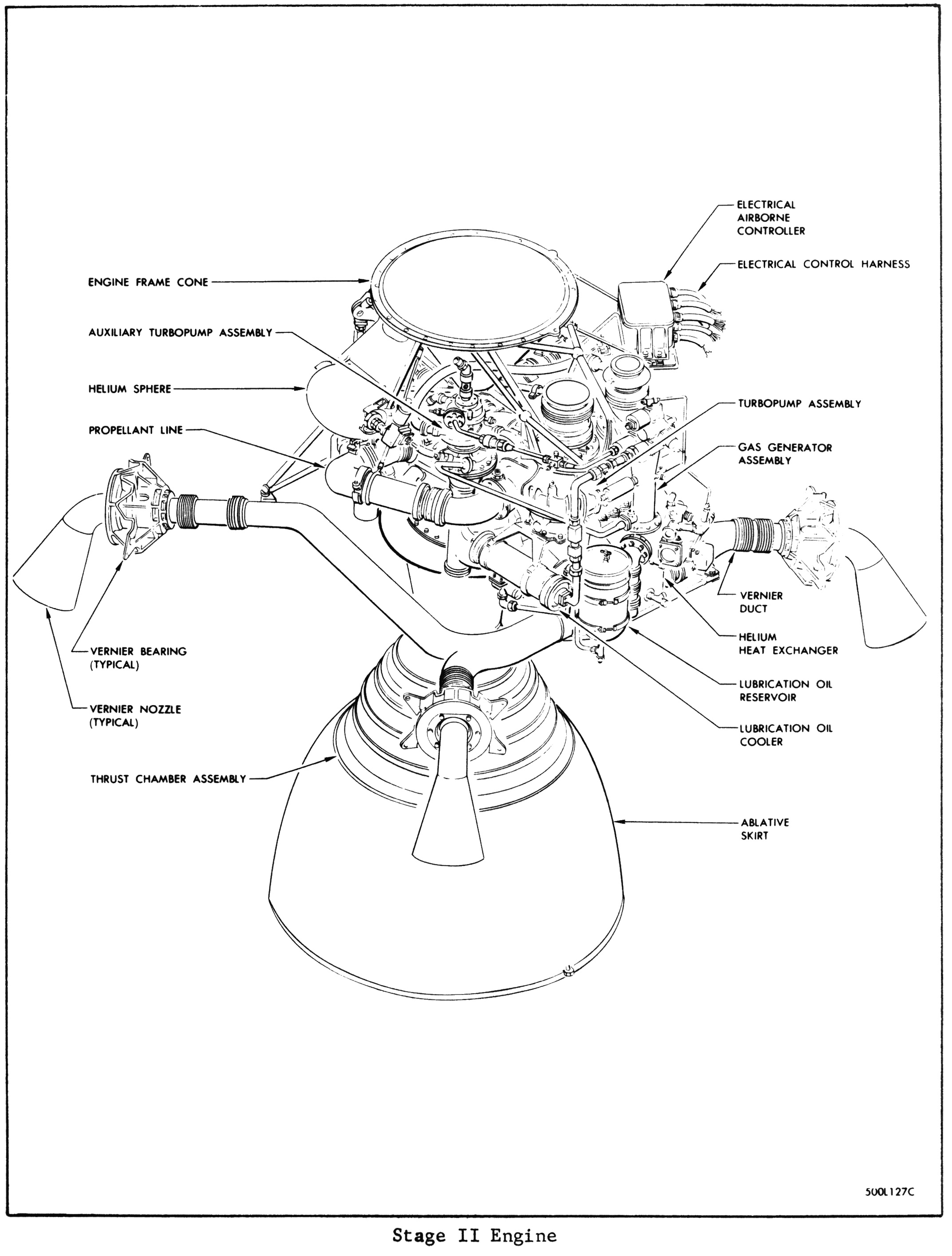
1-247. STAGE II ROCKET ENGINE. The Stage II rocket engine subassembly (figure 1-61), designated LR91-AJ-3, consists of a single thrust chamber assembly and an integrated hot-gas vernier assembly. The thrust chamber operates as the sustainer engine and develops 80,000 pounds of thrust at an altitude of 250,000 feet. The sustainer engine operates after stage separation and accelerates and directs the missile along a programmed trajectory. The verniers provide attitude control during stage separation, roll control during sustainer engine operation, and final trimming control of missile velocity and attitude after sustainer engine shutdown.
1-248. The components that make up the Stage II rocket engine include a thrust chamber assembly, a turbopump assembly (TPA), a gas generator assembly, a hot-gas diversion valve assembly, an auxiliary turbopump assembly (ATPA), vernier components, helium heat exchanger, propellant lines, altitude start components, an airborne controller, and an electrical harness.
1-249. The engine frame is a stainless steel cone with a welded structure of steel tubes. The base of the steel cone is attached to the support structure of the liquid oxygen tank, and the apex of the cone is attached to the thrust chamber assembly. The welded steel tubes support the turbopump and auxiliary turbopump assemblies. Removable rods support the vernier ducts and propellant lines.
1-250. The engine assembly has a thrust chamber assembly which is gimbal mounted and allows directional control of the thrust to provide pitch and yaw control of the missile. The major components of the thrust chamber assembly include a combustion chamber and ablative skirt, an injector, propellant valves, a gimbal assembly, a gimbal manifold and swivel assembly, and an igniter assembly.
1-251. The turbopump assembly (TPA) supplies propellants to the thrust chamber at the flow rates required to develop rated thrust. Incorporated in the turbopump assembly are propellant pumps, a hot-gas turbine, and lubrication equipment.
1-252. The gas generator assembly burns a mixture of liquid oxygen and fuel to develop the hot-gas driving force used by the turbopump assembly, an auxiliary turbopump assembly, vernier components, and a helium heat exchanger. The gas generator assembly consists of a combustion chamber and injector, propellant valves, and igniters.
1-253. The operation of the diversion valve initiates the switching between vernier solo phase and thrust chamber phase during Stage II engine operation. The diversion valve is a three-way poppet valve located at the outlet of the gas generator. The hot gas diversion valve assembly directs hot gas from the gas generator to the turbopump assembly during thrust chamber operation, and by-passes hot gases through the hot-gas bypass line to the helium heat exchanger during vernier solo operation.
1-254. The auxiliary turbopump assembly (ATPA) supplies the gas generator with propellants. The assembly includes an oxidizer pump, a fuel pump, and a hot-gas turbine mounted on a common shaft. The liquid oxygen and fuel pumps are single stage, centrifugal pumps. The housing for the fuel pump forms the main body of the assembly and includes mounting pads, bearing supports, and internal bearing lubrication passages. The turbine is a single stage unit with one rotor and two gas inlets.
1-255. Vernier components include four nozzles, four bearings, and stainless steel hot-gas ducts. The nozzles are placed 90 degrees apart on the outside of the Stage II engine compartment and are controlled by four hydraulic actuators. The nozzles are fastened to the engine compartment framework by bearings that allow a hydraulic servo-actuator to rotate each nozzle through an arc of 140 degrees. The hot-gas ducts conduct hot gases from the helium heat exchanger to the nozzles. During thrust chamber operation, the hot-gas is used after it is exhausted from the turbopump and auxiliary turbopump assemblies into the helium heat exchanger. During vernier solo operation, the hot-gas from the gas generator passes through the bypass line to the helium heat exchanger.
1-256. The helium heat exchanger is installed in the TPA turbine exhaust duct and uses hot gases exhausted from the turbine, or directly from the gas generator. Operation is the same as Stage I.
1-257. The propellant lines are the discharge and suction lines for both the turbopump assembly and the auxiliary turbopump assembly.
1-258. Altitude start components include a spherical helium start bottle and a start valve. The helium start bottle supplies helium at 3000 PSI. The start valve is installed at the outlet of the helium tank, and is solenoid operated. A helium line routes helium from the start valve to the turbine inlet on the auxiliary turbopump assembly. An electrical signal opens the start valve at the same time that the gas generator pilot valve is opened and the gas generator igniters are energized. The high pressure helium starts the auxiliary turbopump assembly and propellants are admitted to the gas generator and ignited. Hot gases from the generator sustain the operation of the auxiliary turbopump assembly, and the start valve is closed.
1-259. The airborne controller is mounted on the engine frame behind the turbopump assembly and relays electrical signals from AGE and the flight controls auto pilot to sequence and control Stage II engine operation.
1-278. The gas generator is started approximately 7 seconds prior to shutdown of Stage I. The gas generator start signal opens the altitude start valve, gas generator pilot valve, and energizes the gas generator igniters. Pressurized helium is released to accelerate the turbine of the auxiliary turbopump assembly. The propellants pressurized by the auxiliary turbopump assembly are sprayed into the combustion chamber of the gas generator and ignited. The hot gases are by-passed the hot-gas diversion valve directly into the helium heat exchanger and exhausted to the vernier. Hot gases are used to sustain operation of the auxiliary turbopump assembly. The verniers operate solo for approximately 4 seconds to provide missile orientation while separation of stages occurs.
1-279. Approximately 11 seconds after the gas generator starts, the thrust chamber-start signal is received. The hot gases are diverted to the turbopump assembly, accelerating the turbopump. The rising fuel pressure opens the thrust chamber propellant valves and propellants are forced into the injector. During the steady-state operation, the verniers provide roll control and the servo-actuators pivot the thrust chamber to compensate for flight path error detected by the missile guidance system. The thrust control transducer and amplifier assembly controls the gas generator control valve to maintain constant thrust.
1-280. With the receipt of the shutdown signal, the hot-gas diversion valve is returned to the bypass position, terminating the turbopump assembly operation. The pilot valve closes and vents actuation fuel, which allows the propellant valves to close, terminating thrust chamber operation. The gas generator and auxiliary turbopump assembly continue to operate and provide vernier thrust for final missile velocity and orientation trimming.
1-281. When the signal for vernier shutdown is received, the gas generator valve pilot valve closes. The actuation fuel is vented, allowing the gas generator propellant valves to close. The gas generator is shut down and this terminates the operation of the auxiliary turbopump assembly and shut down the Stage II rocket engine.