
Titan I First Stage Engines (LR-87)
The Titan missiles used the LR-87 as its first stage engines.
The LR-87 was powered by liquid oxygen (LOX) and RP-1 in the Titan I. In the Titan II, they were powered by Aerozine-50 (a 50-50 blend of unsymmetrical dimethylhydrazine [UDMH] and hydrazine) and nitrogen tetroxide (N2O4). I've found relatively little documentation for the UDMH/N2O4 version of the engine, or the specific changes which were necessary to convert to the new propellants.
Click image for a 2133x2832 pixel version of this image in a new window.
Taken from p. 1-99 (p. 6 in Section
7 [direct link to 20.3 meg PDF]; of the T.O.
21M-HGM25A-1.1, Technical Manual - Operational and Organization Maintenance
USAF Model HGM-25A Missile Weapon System Operation)
Scan by Titan I Epitaph
Extraction and clean-up by heroicrelics.org.

Click image for a 2126x2828 pixel version of this image in a new window.
Taken from p. 1-102 (p. 9 in Section
7 [direct link to 20.3 meg PDF]; of the T.O.
21M-HGM25A-1.1, Technical Manual - Operational and Organization Maintenance
USAF Model HGM-25A Missile Weapon System Operation)
Scan by Titan I Epitaph
Extraction and clean-up by heroicrelics.org.
- 1. Liquid Oxygen Pump
- 2. Fuel Pump
- 3. Hot Gas Turbine
- 4. Helium Heat Exchanger
- 5. Gimbal Bearing Assembly
- 6. Gimbal Mount
- 7. Gimbal Actuation Arm
- 8. Servo·Actuator Attachment
- 9. Injector
- 10. Liquid Oxygen Torus
- 11. Fuel Torus
- 12. Thrust Chamber Valve Actuator
- 13. Igniter
- 14. Combustion Chamber
- 15. Thrust Chamber No. 1
- 16. Hot Gas Exhaust Cone
- 17. Thrust Chamber No. 2
- 18. Overboard Drain Lines
- 19. Pressure Sequence Valve
- 20. Fuel Valve
- 21. Propellant Feeder Manifold
- 22. Liquid Oxygen Valve
- 23. Turbopump Assembly Gearbox
The rest of this text on this page is excerpted from T.O. 21M-HGM25A-1.1, Technical Manual - Operational and Organization Maintenance USAF Model HGM-25A Missile Weapon System Operation (discussing the LR-87 as it was used by the Titan I), with some minor edits by heroicrelics. The numbers at the beginning of each paragraph indicate the paragraph number in the source document.
1-236. ENGINE SYSTEM.
1-237. The rocket engine system includes the Stage I and Stage II engines and the associated aerospace operating equipment (AOE). The engines are physically and functionally complete and separate assemblies, and are installed in their respective missile stages. The rocket engines are connected to the ground operating equipment through the missile umbilicals.
1-238. The engines burn liquid oxygen and RP-l fuel, and exhaust the resulting hot gases at supersonic velocities. The AOE starts the Stage I engine after checking that both engines are ready to fire. The Stage I engine (booster engine) is started on the ground and provides the thrust for missile lift off and initial acceleration. The Stage II engine is started at altitude and sustains the acceleration and establishes the programmed final velocity. The total operating time of both engines approaches 6 minutes for maximum range.
1-242. The engine start equipment is used to initiate operation of the Stage I engine. The start equipment includes two banks of nitrogen K-bottles pressurized to 3000 PSI. . . . When the nitrogen is released by the start valve, the turbine of the turbopump assemblies of the Stage I engine subassemblies are accelerated and drive the turbopump [heroicrelics: Presumably, this is the high-pitched "scream" one hears just prior to engine start-up]. The flow of nitrogen to the turbines is cut off when the gas generators fire and provide sufficient power to sustain operation of the turbopump assemblies.
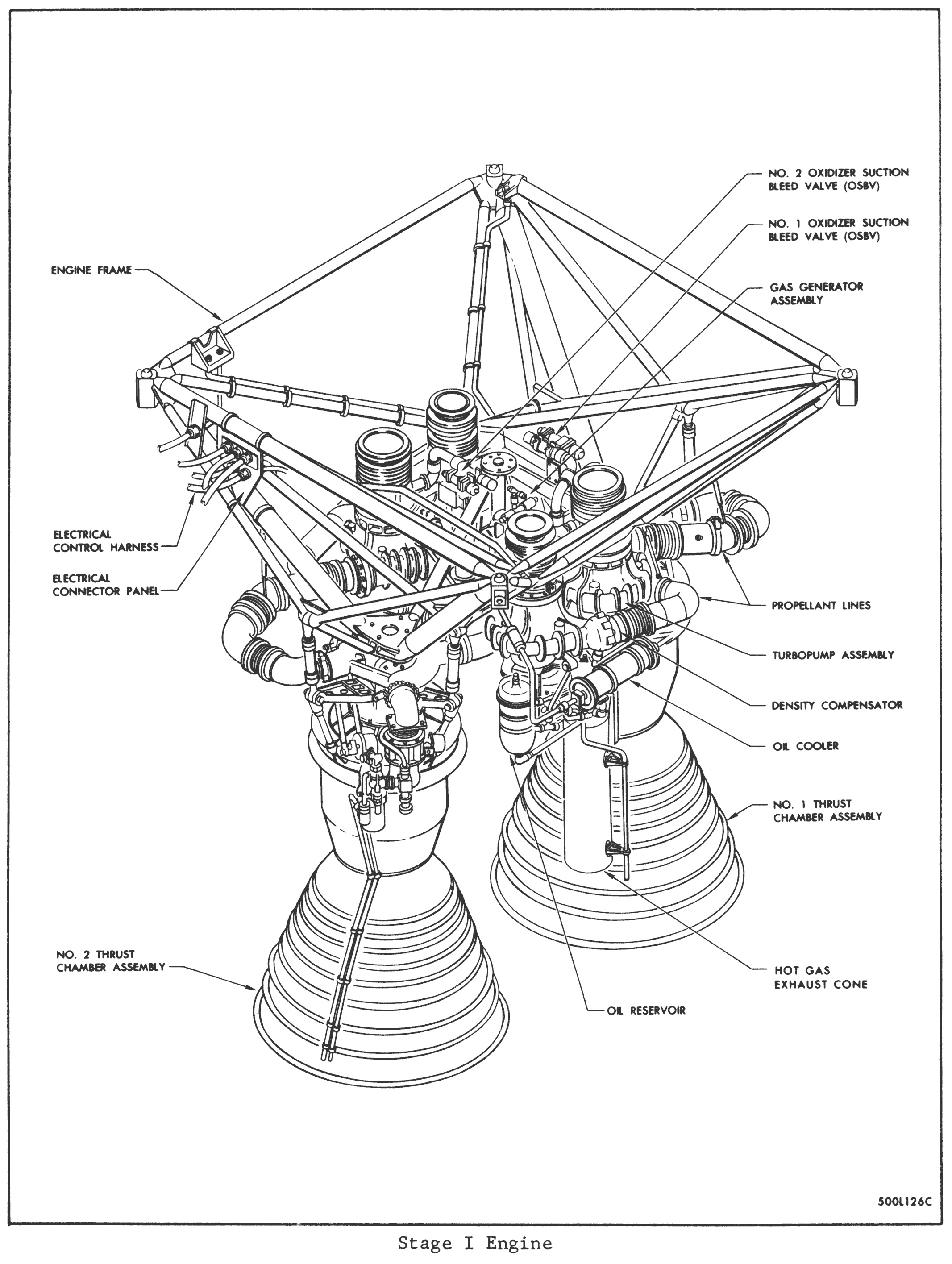
1-243. STAGE I ROCKET ENGINE. The Stage I rocket engine, designated LR87-AJ-3, consists of two engine subassemblies. The two subassemblies develop a total of 300,000 pounds of thrust and are mounted on a common engine frame that transfers the thrust to the missile airframe. The subassemblies are similar and are interconnected by instrumentation and electrical components. The subassemblies are started and shut down simultaneously, and each must reach 77 percent of its rated thrust before the missile is released from the launcher platform. Each engine subassembly includes a thrust chamber assembly, a turbopump assembly (TPA), a gas generator assembly, and propellant lines and valves. One subassembly also contains a helium heat exchanger.
1-244. The turbopump assembly (TPA) in each engine subassembly includes propellant pumps, a hot gas turbine, and lubrication equipment.
1-245. The gas generator assembly generates hot gases to drive the turbopump assembly. The gas generator assembly is bolted to the hot-gas inlet of the turbopump turbine. The gas generator includes a combustion chamber and injector, a valve assembly, and igniters. Two pyrotechnic igniters are used to start the burning of propellants in the combustion chamber.
1-246. The helium heat exchanger is installed on the turbine of the turbopump assembly of engine subassembly number two, and uses hot gases exhausted from the turbine to raise the temperature and expand the helium used to pressurize the propellant tanks. The helium flows from the storage spheres in the Stage I liquid oxygen tanks to the heat exchanger, circulates through a coil of tubing, and flows back to pressurize both propellant tanks of Stage I. The hot gases are exhausted from the heat exchanger through an exhaust duct and add approximately 600 pounds to the engine thrust.
1-262. OPERATION. During countdown, the liquid oxygen tanks of both missile stages are filled and pressurized, and both engines are bled and checked. If both engines, the ground start system, and the other missile systems fulfill the go requirements, the Stage I engine is fired. The missile is released from the launcher when both subassemblies of the Stage I rocket engine reach 77 percent thrust. The engine control system signals the launch sequencer for shutdown if both thrust chambers of the Stage I engine do not reach 77 percent thrust within a specified period of time.
1-266. When the fire-switch-one signal is received to start the rocket engine, the ground based nitrogen start valve is opened and the thrust chamber igniters are energized. With the opening of the nitrogen start valve, nitrogen at 3000 PSI enters the turbines of the turbopump assembly to start the propellant pumps rotating to supply the propellants to the thrust chamber [heroicrelics: again, this is presumably the high-pitched "scream" one hears just prior to engine start-up].
1-267. The rising fuel pressure from the turbopump assembly positions the thrust chamber valve pressure sequencing valve to the open position, admitting actuation fuel to the actuator. The actuator initiates the opening of the fuel valve and the fuel fills the combustion chamber cooling jacket.
1-268. The connecting rod from the fuel valve opens the oxidizer valve to admit liquid oxygen to the thrust chamber injector. The fuel enters the injector from the combustion chamber cooling jacket. The propellants are sprayed into the combustion chamber and ignited.
1-269. The position switch on the thrust chamber fuel valve assembly is actuated as the fuel valve opens, providing an electrical signal to open the gas generator valve pilot valve and energize the gas generator igniters. The pilot valve admits actuation fuel to the actuator to open the propellant valves. Propellants from the turbopump assembly are admitted to the injector and sprayed into the gas generator combustion chamber where they are ignited.
1-270. The position switch on the gas generator valve assembly is actuated as the valve opens, providing an electrical signal for closing the nitrogen start valve and de-energizing the thrust chamber and gas generator igniters. The hot gases developed by the gas generator continue to accelerate and drive the turbopump assembly. The turbopump assembly supplies propellants to the thrust chamber and gas generator. The rising pressure in the combustion chamber closes the thrust chamber pressure switch to complete the start missile release circuit.
1-271. The hot gas expelled by the gas generator drives the turbopump assembly. The hot gas developed by the thrust chamber provides the thrust for missile liftoff and initial acceleration.