
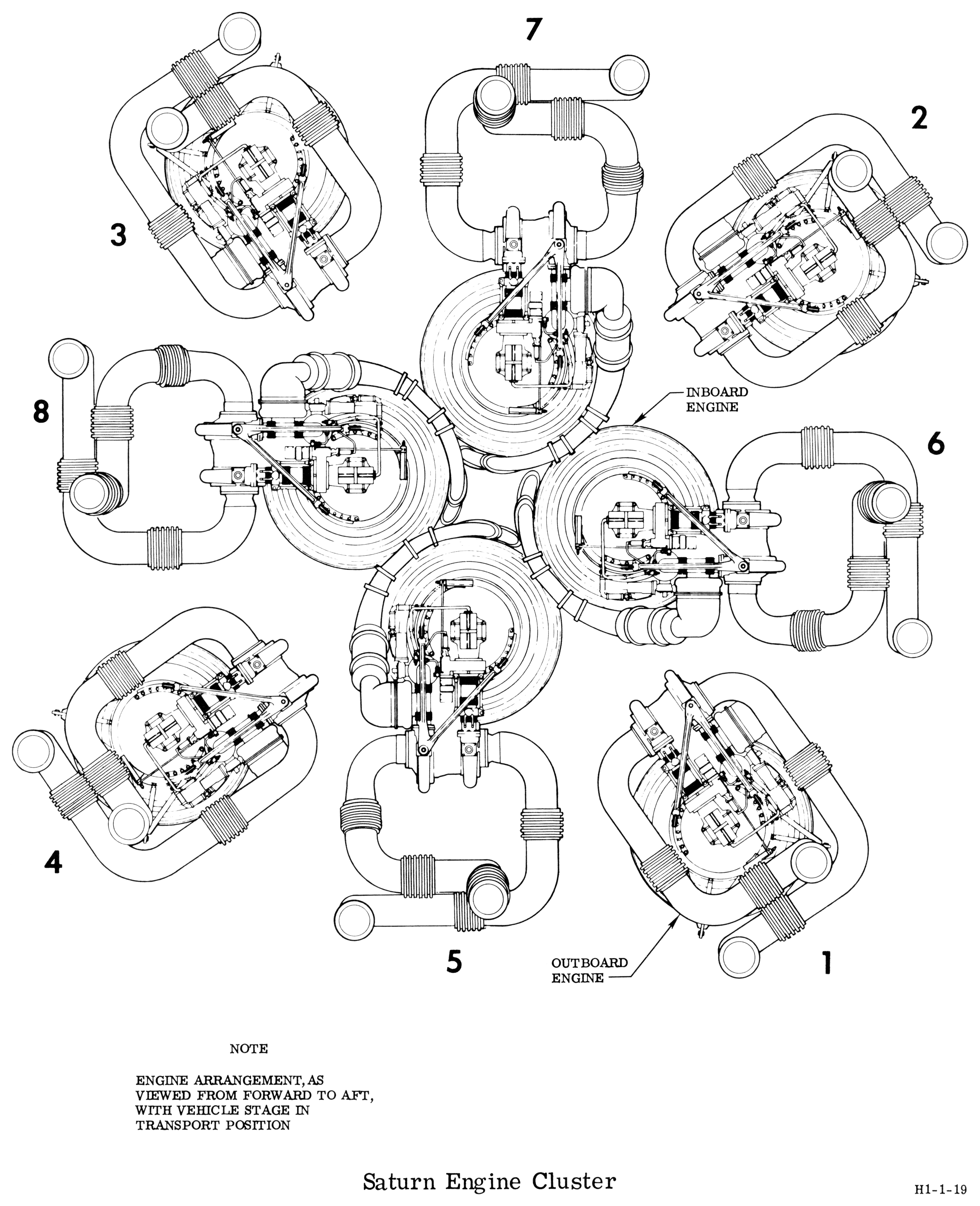
Saturn I/IB H-1 Rocket Engine Wraparound Suction Lines
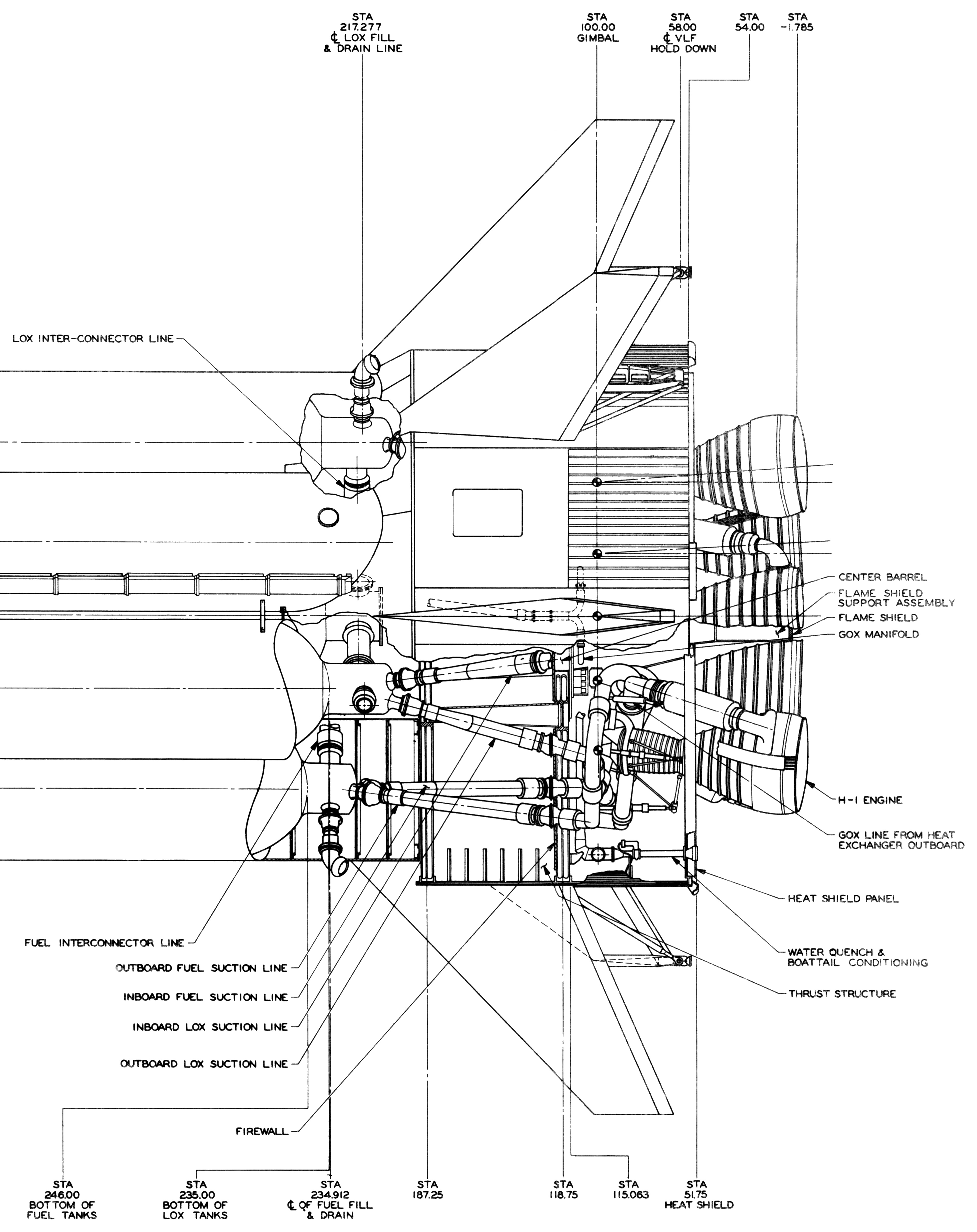
The turbopumps on each of the eight H-1 rocket engines in the Saturn I and Saturn IB first stages were fed by by wraparound suction lines. The engines' fuel and LOX suction line were each eight inches in diameter.
Click image for a 4221x5193 pixel version of this image in a new window.
From the page 1-6 of the H-1 Rocket Engine Models H-1C and H-1D Technical
Manual: Engine Data. Located in the Saturn V Collection, Dept. of Archives/Special
Collections, M. Louis Salmon Library, University of Alabama in Huntsville,
which also makes this document available as a 14.4
megabyte PDF.
Scan and cleanup by heroicrelics.
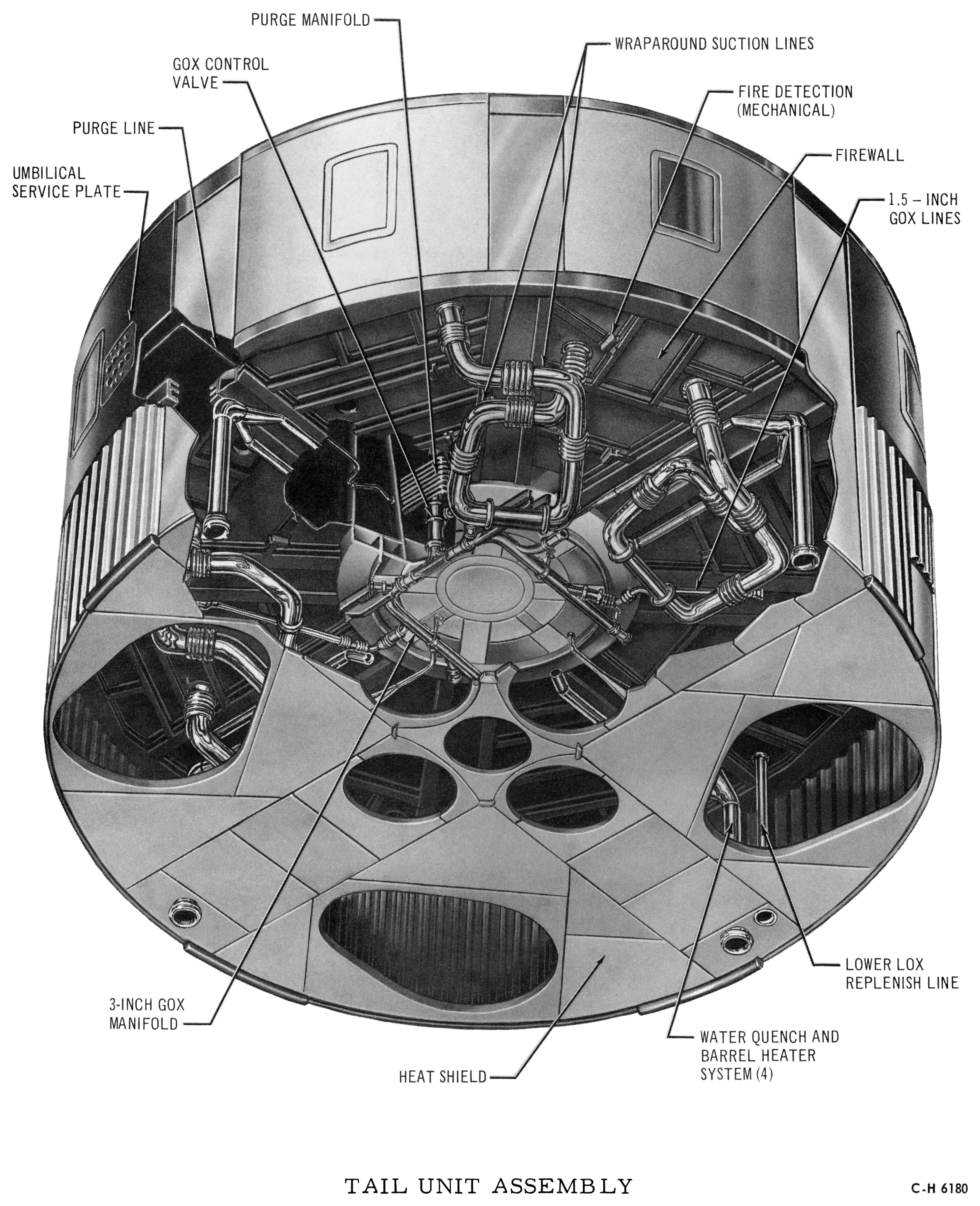
Each fuel container fed into a lower manifold, interconnecting the four fuel container sumps, maintaining an approximately uniform fuel level in the containers. In the event of an engine failure, the fuel manifold would distribute the failed engine's fuel to the remaining engines. Two fuel suction lines were connected to each container's sump, one feeding an inboard engine and one feeding an outboard engine. Near the top of each fuel suction line was a prevalve which remained open except in the case of emergency, such as an engine failure or a broken line.
A document dated September 1968 notes that each fuel suction line supplied fuel at a rate of 227 pounds per second. This was one month before the launch of Apollo 7 (AS-205), the last Saturn IB equipped with the 200,000 lb. thrust version of the H-1 engine. Subsequent S-IB stages were equipped with the 205,000 lb. thrust version of the H-1 (which would require more fuel per second), so I'm not certain as to exactly which version of the engine this flow rate pertained.
The LOX containers were similarly manifolded (the manifold of course included the 105" center LOX container), and each LOX container's sump similarly provided LOX to one inboard and one outboard engine. The suction lines provided LOX at the rate of 505 pounds per second (again with the uncertainty as to the specific version of the engine to which this flow rate applied).
Click image for a 3953x4863 pixel version of this image in a new window.
From the page 7 (page 12 in the PDF) of my SA-5 Saturn I Block II Vehicle
Description.
Scan and cleanup by heroicrelics.
A fuel conditioning system bubbled GN2 from a ground source through each fuel suction line to maintain a homogeneous temperature in each suction line. The nitrogen bubbling was initiated prior to LOX loading and continued until fuel container pressurization. The GN2 was vented through the fuel container vent system.
Similarly, a ground source supplied helium to bubble into the LOX suction lines creating LOX circulation and maintaining a suitable temperature at the pump inlets.
Click image for a 3820x4815 pixel version of this image in a new window.
Adapted from page 5 of the AS-207
Vehicle Systems Information Drawings.
Scan, cleanup, and adaptation by heroicrelics.
I don't believe I've ever read anything regarding the reason for wraparound design of the propellant suction lines. Since the turbopumps gimbal with the engine and the suction lines are equipped with two bellows sections, I assume this arrangement allowed for the required flexibility during engine gimballing (and any movement associated with engine vibration). A similar arrangement was used with the Jupiter missile high-pressure ducts. Recall that on the Jupiter, the turbopumps were on the fixed portion of the engine and the thrust chamber gimballed, so the high-pressure ducts would have undergone similar motion as the wraparound lines on the H-1.
The bulk of the descriptive text on this page was taken, largely verbatim, from the Apollo Systems Description, Volume II: Saturn Launch Vehicles.