Return to Kansas Cosmosphere
LR-89 (Atlas Booster) Engine
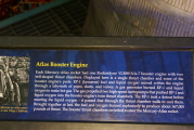
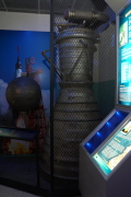
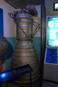
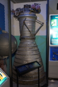
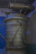
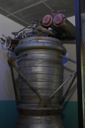
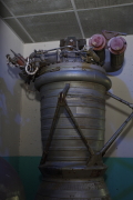
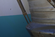
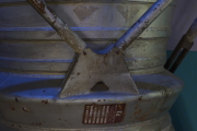
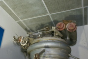
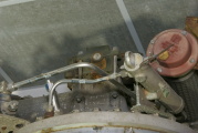
In another corner of the Cold War Gallery's Blockhouse 5/6 exhibit is an LR-80 (Atlas booster) rocket engine.
The entire Atlas missile engine system consisted of two LR-89 (booster) engines and one LR-105 (sustainer) engine. The exact configuration of the the engine system changed several times: In the MA-3 configuration, the booster engines' gas generators and turbopumps were mounted with each thrust chamber (i.e., a self-contained engine), but in the earlier MA-2 and later MA-5 configurations, the two LR-89s shared a single gas generator and the turbopumps were mounted centrally, and so the two thrust chambers were considered a single engine (similar to most Soviet engines).
In any case, the two thrust chambers in the engine system appear to be mirror images of each other, with the high-pressure ducts entering the thrust chamber in opposite fashions.
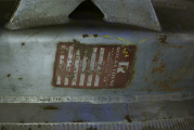
As per the report, Performance Data for Individual Atlas MA-2 and MA-5 Engines, this particular engine (NA115101) was part of an MA-5 engine system (in which the two LR-89 thrust chambers shared a single gas generator). This engine underwent its final acceptance test on September 23, 1960 and the pair of LR-89s generated a total of 309,016 pounds of thrust. While I'm uncertain as to which thrust chamber in the pair this particular thrust chamber was, the no. 1 thrust chamber consumed 424.9 pounds of LOX and 179.9 pounds of RP-1 per second, while the no. 2 thrust chamber consumed 425.1 pounds of LOX and 177.9 pounds of RP-1 per second. The pair's gas generator (which was run fuel-rich to reduce combustion temperatures) consumed 6.39 pounds of LOX and 18.86 pounds of fuel per second.
From the mid-1950s through the late 1960s, the Jupiter, Thor, Atlas booster, and H-1 rocket engines were manufactured and tested at a Rocketdyne facility in Air Force Plant No. 65, located in Neosho, MO.
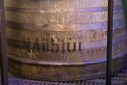
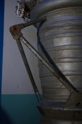
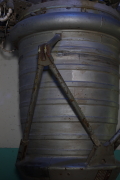
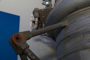
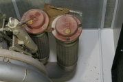
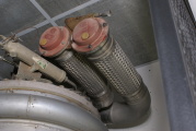
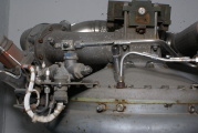
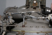
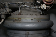
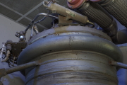
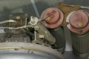
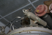
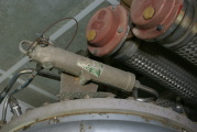
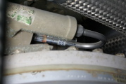
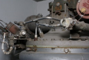
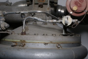
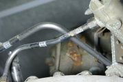
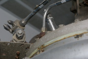
This is the only LR-89 I've encountered (other than those installed in Atlas missiles), so I took some detailed photos of the engine's forward end. The engine being as tall as it is and the DSLR that I had at the time having no LCD panel viewfinder, many of these photos were taken by holding the camera over my head and "shooting blind."
See my Atlas engine-related resources or SiloWorld for additional Atlas engine diagrams.
Return to Kansas Cosmosphere
