| Prev |
heroicrelics.org U.S. Space & Rocket Center Site Index Mercury-Redstone Tail Unit Interior Gallery |
Next |
dsc94148.jpg
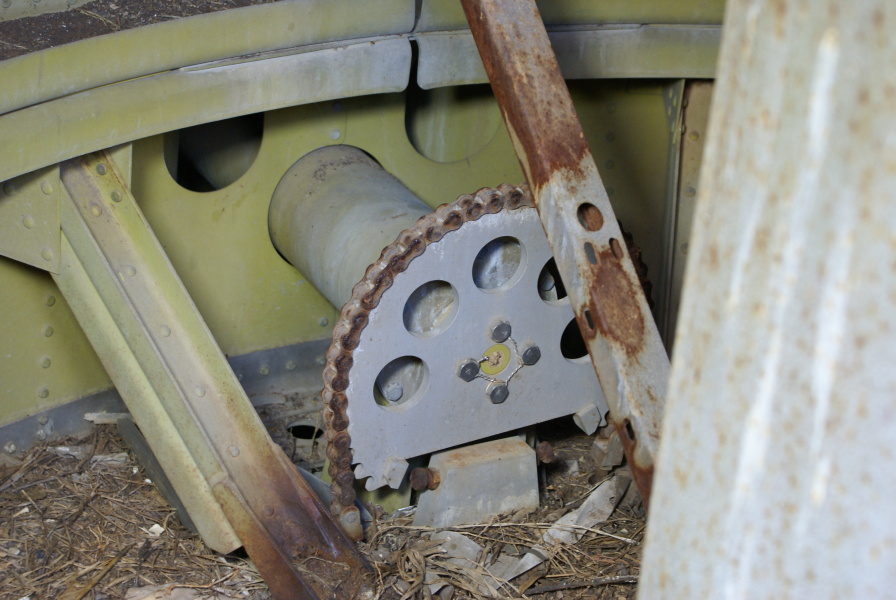
View of the booster's air rudder/jet vane actuators.
Picture 2 of 4.
The Redstone was an early missile, and the state of the art did not yet support a gimballed engine. In order to control the missile's attitude, the Redstone (like the V-2 before it) was equipped with four actuators, each of which operated both a fin-mounted air rudder and a jet vane in the engine's exhaust stream.
During the first moments of flight, the missile was controlled by the carbon jet vanes located within the engine exhaust. When the missile reached a velocity sufficient for it to become aerodynamically stable, the air rudders took over the control function.
For simplicity, both the air rudder and and corresponding jet vane were interconnected, both operating simultaneously.
I am uncertain as to where the actual, electrically-powered actuator is located. Based on the size of an air vane actuators in the aft unit, the visible portion here is not the actuator itself. The drive unit may be located in the fin (and there were certainly several bundles of electrical wiring going to/from the fin which could support this), with a shaft leading to the gear and chain to operate the jet vane below. Alternatively, the drive unit may be located at the jet vane below, with the chain driving the gear connected to a shaft to drive the air rudders.
| Time picture taken | Tue Sep 10 13:49:26 2013 |
| Location picture taken |
Rocket Park U.S. Space & Rocket Center Huntsville, AL |
| Prev |
heroicrelics.org U.S. Space & Rocket Center Site Index Mercury-Redstone Tail Unit Interior Gallery |
Next |