| Prev |
heroicrelics.org Udvar-Hazy Center Site Index Cut-Away V-2 Engine Gallery |
Next |
dsc77121.jpg
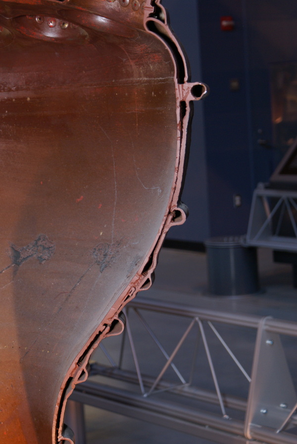
Detail of the double-walled combustion chamber wall.
Picture 2 of 2.
Note the rows of film cooling holes on the interior of the combustion chamber (one just aft of the burner cups; another just below center of this photo, where the combustion chamber wall is scarred; and one just forward of the throat). Each row of holes corresponds to a film cooling manifold on the exterior of the engine, fed by four film cooling pipes.
Between the two walls at each cooling manifold is a spacer. The spacers have coaxially-drilled holes to allow fuel to flow up between the combustion chamber walls. These spacers also have holes drilled between the film cooling manifold and the holes through the inner wall to admit fuel for film cooling into the combustion chamber.

| Time picture taken | Sun Jun 19 14:38:20 2011 |
| Location picture taken |
Ground Level James S. McDonnell Space Hangar Udvar Hazy Center Chantilly, VA |
| Prev |
heroicrelics.org Udvar-Hazy Center Site Index Cut-Away V-2 Engine Gallery |
Next |