| Prev |
heroicrelics.org Stennis Space Center Site Index J-2 Engine Gallery |
Next |
dsc06490.jpg
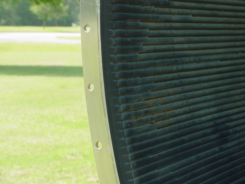
View of the reverse flow manifold.
Fuel flowed down the thrust chamber's half-length regenerative cooling tubes to the reverse flow manifold, where it flowed back up the full-length tubes to the fuel manifold and then on to the injector.
| Time picture taken | Fri Jun 18 10:02:00 2004 |
| Location picture taken |
Rocket Park Visitor Center Stennis Space Center, MS |
| Prev | J-2 Engine Gallery | Next |