| Prev |
heroicrelics.org Stennis Space Center Site Index F-1 Engine Gallery |
Next |
dsc06520.jpg
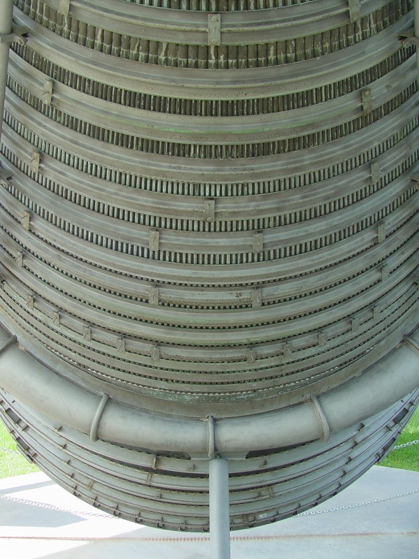
Picture taken standing under the forward end of the F-1, showing the thrust chamber, turbine exhaust manifold, nozzle extension, and the bracket supporting the aft end of the engine as it is displayed.
Note between the top two hatbands where the tubes comprising the thrust chamber become bifurcated (split in two).
Also note the rectangular tabs with studs welded to the hatbands on the engine proper; these would support the thermal insulation which is installed on the engine for launch or static test.
| Time picture taken | Fri Jun 18 10:15:32 2004 |
| Location picture taken | Rocket Park Visitor Center Stennis Space Center, MS |
| Prev | F-1 Engine Gallery | Next |