| Prev |
heroicrelics.org Stafford Air & Space Museum Site Index F-1 Engine Gallery |
Next |
dsc46653.jpg
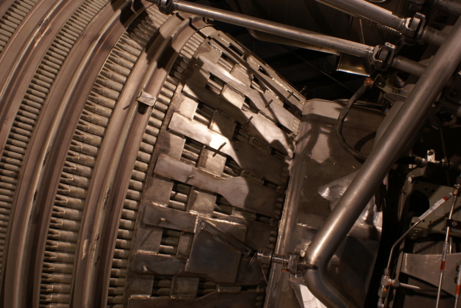
A detail of the forward part of the thrust chamber.
The two sections of tubing at the top appear to be the heat exchanger helium and gaseous oxygen supply lines.
The studs sticking out from the various tabs are used to support the engine's thermal insulation.
Toward the left of the picture, note where the tubes comprising the thrust chamber "bifurcate", or split in two.
| Time picture taken | Thu Jul 31 11:26:22 2008 |
| Location picture taken |
Apollo Gallery Stafford Air & Space Museum Weatherford, Oklahoma |
| Prev |
heroicrelics.org Stafford Air & Space Museum Site Index F-1 Engine Gallery |
Next |