| Prev |
heroicrelics.org Science Museum Oklahoma Site Index J-2 Engine Gallery |
Next |
dscc3899.jpg
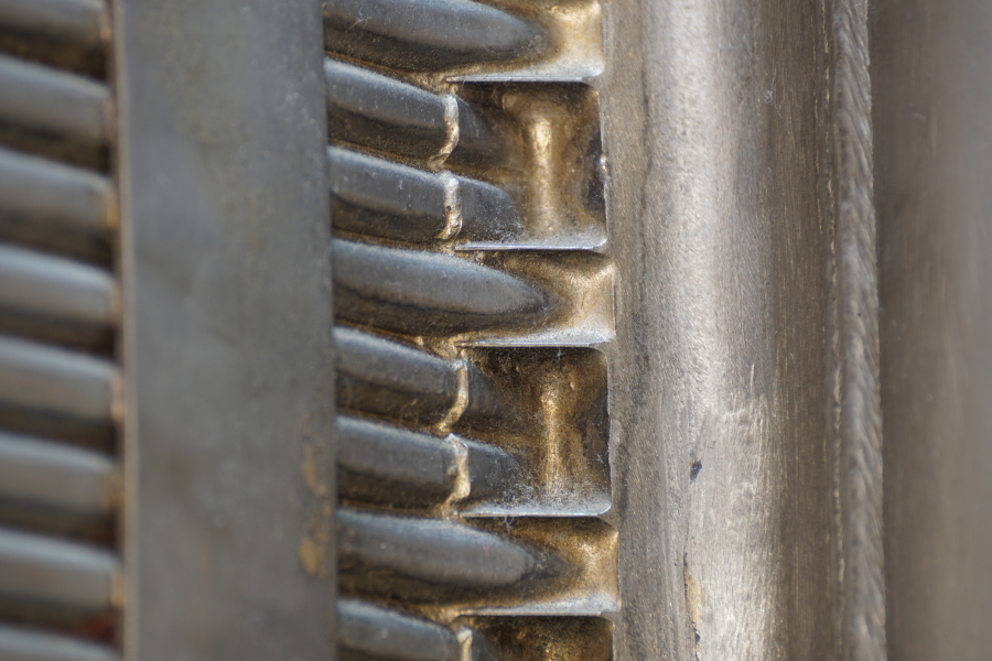
Detail of the aft side of the fuel manifold.
Picture 2 of 2.
The J-2 thrust chamber is constructed of 360 full-length "up" tubes running from reverse-flow manifold to the the injector, plus an additional 180 "down" tubes running from here at the fuel manifold to the reverse-flow manifold. This "pass-and-a-half" construction increases the number of tubes comprising the thrust chamber as the diameter of the nozzle increases, allowing for a high expansion ratio.
So, there are two "up" tubes for each "down" tube, and this is obvious here: The two "up" tubes have a bracket from the fuel manifold brazed onto them, while the "down" tube originates in the fuel manifold and runs between the brackets.
This is also clearly visible in the thrust chamber interior. The gaps between the sets of "up" tubes to make room for the "down" tube also serve as a slot through which the turbine exhaust gas (from the exhaust manifold, just forward of the fuel manifold) enters the combustion chamber.
| Time picture taken | Sun Apr 10 16:31:04 2016 |
| Location picture taken |
Open-Air Exhibit Gallery Science Museum Oklahoma (formerly the Omniplex) Oklahoma City, OK |
| Prev |
heroicrelics.org Science Museum Oklahoma Site Index J-2 Engine Gallery |
Next |