| Prev |
heroicrelics.org Marshall Space Flight Center Site Index J-2 Engine Thrust Chamber J-2111 Gallery |
Next |
dsca6428.jpg
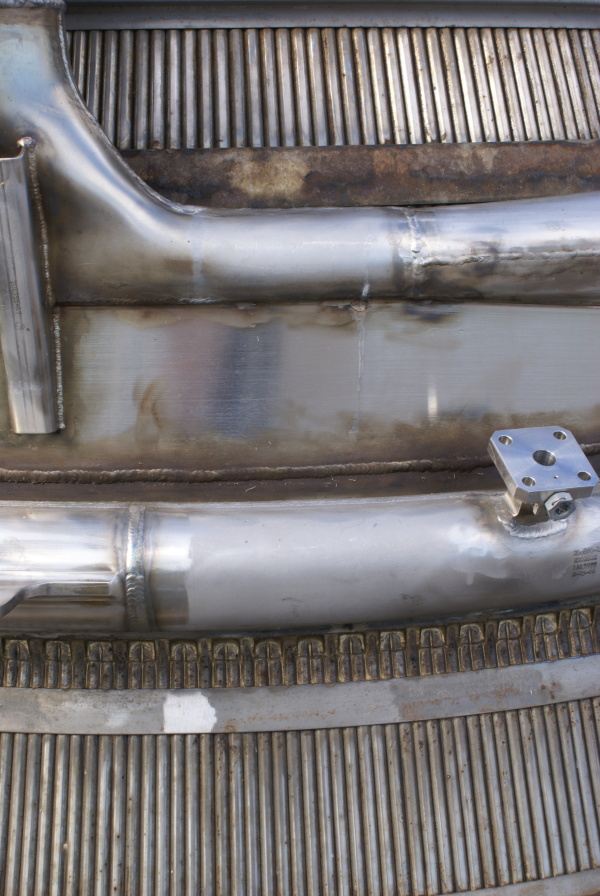
Detail of the thrust chamber at the point at which the additional 180 tubes are added to the 360 full-length tubes comprising the thrust chamber at the fuel manifold. The addition of these tubes is best seen on the interior of the thrust chamber.
Picture 1 of 4.
The J-2 thrust chamber is constructed of 360 full-length "up" tubes running from the reverse-flow manifold to the the injector, plus an additional 180 "down" tubes running from the fuel manifold to the reverse-flow manifold. This "pass-and-a-half" construction increases the number of tubes comprising the thrust chamber as the diameter of the nozzle increases, allowing for a high expansion ratio.
In this photo it is possible to compare the regenerative cooling tubes forward of the exhaust manifold (top of this photo), where the thrust chamber consists solely of the 360 "up" tubes, and the cooling tubes aft of the fuel manifold, where the 180 "down" tubes are added.
There are two "up" tubes for each "down" tube, presumably due to the expansion of the liquid hydrogen to hydrogen gas as the fuel absorbs heat from the interior of the thrust chamber wall.
So, every third tube here is a newly-introduced "down" tube. Note the fuel manifold brackets brazed onto sets to two "up" tubes; the "down" tubes are introduced between these brackets.
| Time picture taken | Tue Sep 16 09:08:56 2014 |
| Location picture taken |
Building 4205 Marshall Space Flight Center Huntsville, AL |
| Prev |
heroicrelics.org Marshall Space Flight Center Site Index J-2 Engine Thrust Chamber J-2111 Gallery |
Next |