| Prev |
heroicrelics.org Marshall Space Flight Center Site Index J-2 Engine Thrust Chamber J-2111 Gallery |
Next |
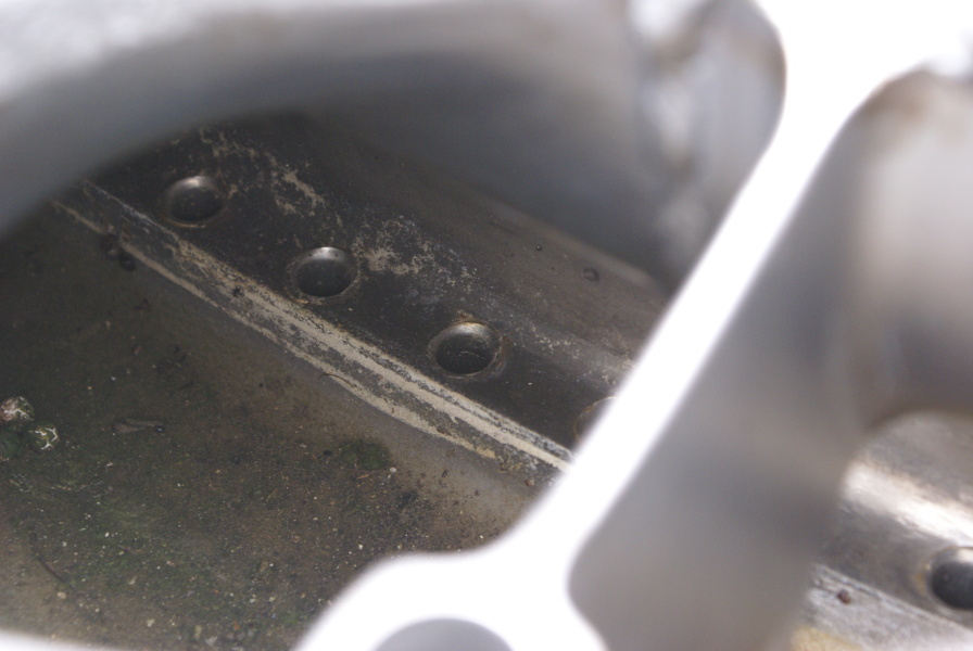
dsc93161.jpg
Detail of the interior of the fuel manifold inlet.
Picture 2 of 5.
Liquid hydrogen from the turbopump is routed to the fuel manifold, where it enters the ends of these half-length regenerative cooling tubes. The fuel then travels through these tubes, down the thrust chamber, to the exit plane. There the reverse-flow manifold (variously called a fuel return manifold or turnaround manifold on other rocket engines) routes the hydrogen up the full-length regenerative cooling tubes to the injector.
The J-2 thrust chamber is constructed of 360 full-length "up" tubes running from reverse-flow manifold to the the injector, plus an additional 180 "down" tubes running from the fuel manifold to the reverse-flow manifold. This "pass-and-a-half" construction increases the number of tubes comprising the thrust chamber as the diameter of the nozzle increases, allowing for a high expansion ratio.
| Time picture taken | Mon Sep 9 13:11:08 2013 |
| Location picture taken |
Building 4205 Marshall Space Flight Center Huntsville, AL |
| Prev |
heroicrelics.org Marshall Space Flight Center Site Index J-2 Engine Thrust Chamber J-2111 Gallery |
Next |