| Prev |
heroicrelics.org Marshall Space Flight Center Site Index J-2 Engine (Building 4205) Gallery |
Next |
dsc67065.jpg
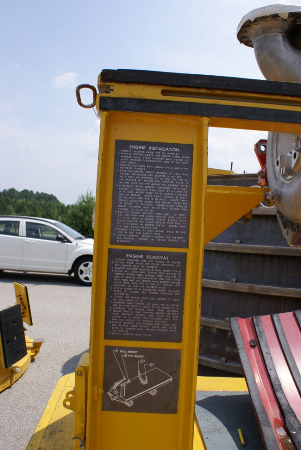
Three labels on an upright member on the forward end of the engine handler.
The top label reads
ENGINE INSTALLATION
- Remove decking from top of handler.
- Remove engine cover and cover sling from handler base. Stow handler dust cover. Replace decking (corrugated side up for shipping only).
- Remove cap from ball mount (Pt. A) and stow between gussets.
- Position engine above handler so that ball socket on engine red adapter is in line with ball on handler (Pt. A) and the pin in the bearing at engine red adapter plate is in line with the pin mount on handler (Pt. B).
- Carefully move engine forward until ball socket is directly over ball (Pt. A) and pin is in slot above hole (Pt. B). Lower forward end of engine. Check that socket is seated on ball and pin is in hole. Check that spring actuated slider has moved over pin to secure it in place. Using Allen wrench insert fastener assy in to ball socket and torque to 20-40 in lbs.
- For aft mount rotate yoke assy to vertical position and align hole in yoke lug (Pt. C1) with hole in engine clevis. Secure with quick release pin. Align hole in yoke lug (Pt. C2) with hole in engine clevis. Secure with pin and quick release pin.
- Torque fastner[sic] at ball mount (Pt. A) to 400-500 in lbs. and safety wire.
- Install engine security cover per instruction manual. Stored in cover pocket. (If required.).
The middle label reads
ENGINE REMOVAL
- Attach forward and aft slings to engine.
- Secure wing studs on cover retaining strips around base of handler.
- Remove fastener inserted in ball mount (Pt. A).
- Using aft sling only, slowly hoist engine to remove weight from handler yoke lugs (Pts. C1 and C2). Remove pins from both yoke lugs. Hand hold yoke and lift engine until engine clevises clear yoke lugs (Pts. C1 and C2). Rotate yoke forward to rest on handler base.
- At pin mount (Pt. B) disengage spring actuated slider by pulling red handle forward and turning 90°.
- Slowly lift engine until ball socket is clear of ball mount (Pt. A).
- Carefully move engine aft until pin in engine red adapter plate is clear of pin mount (Pt. B).
- Carefully lift engine away from handler.
- Secure yoke to yoke supports. Remove cap from stud between gussets and place on ball mount (Pt. A). Secure with fastener assy. Return red handle to original position.
- Remove decking and handler dust cover stored in base. Store security cover and cover sling in handler base. Replace decking with flat side up.
- Install handler dust cover.
The bottom label is a diagram:
Pt. A, the ball mount, is at forward left.
Pt. B, the pin mount, is at forward right.
Pts. C1 and C2 are at middle right and middle left, respectively.
| Time picture taken | Fri Jul 10 14:23:53 2009 |
| Location picture taken |
Building 4205 Marshall Space Flight Center Huntsville, AL |
| Prev |
heroicrelics.org Marshall Space Flight Center Site Index J-2 Engine (Building 4205) Gallery |
Next |