| Prev |
heroicrelics.org Marshall Space Flight Center Site Index F-1 Engine F-4023 Gallery |
Next |
dsca7358.jpg
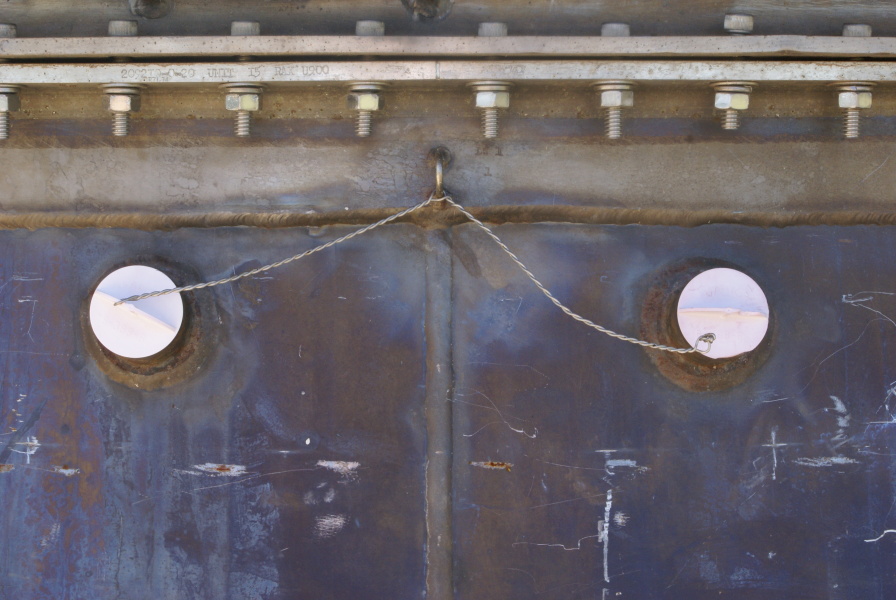
View of the nozzle extension's two pyrotechnic igniter bosses.
Picture 2 of 3.
The igniter bosses have protective closures installed.
Note the lockwire, anchored in a loop on the forward end of the nozzle extension, for the closures.
Fuel-rich turbine exhaust gas would enter the nozzle extension from the turbine exhaust manifold. This gas, relatively cool compared to the combustion gases of the main combustion chamber, would cool the double-walled nozzle extension.
The inner wall of the nozzle extension was comprised of shingles with gaps where the shingles overlap. The turbine exhaust gas exited the nozzle extension through these gaps, providing film cooling for the inner nozzle extension wall.
The pyrotechnic igniters would ignite this fuel-rich gas, although I'm unclear as to why this was necessary. Perhaps it was so that the gas was already burning and didn't suffer a hard ignition when it entered the main combustion chamber's exhaust stream.

| Time picture taken | Tue Sep 16 11:09:04 2014 |
| Location picture taken |
Building 4205 Marshall Space Flight Center Huntsville, AL |
| Prev |
heroicrelics.org Marshall Space Flight Center Site Index F-1 Engine F-4023 Gallery |
Next |