| Prev |
heroicrelics.org Marshall Space Flight Center Site Index F-1 Engine (Building 4200) Gallery |
Next |
dsc94734.jpg
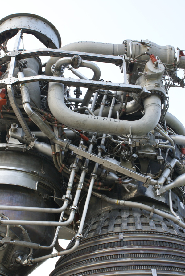
View of the lines leading to and from the heat exchanger.
Picture 2 of 2.
The three lines grouped together leading to the forward end of the engine are, from right to left, the helium supply line, the helium return line, and the LOX return line. The helium supply line supplies gaseous helium from high-pressure helium bottles in the S-IC's LOX tank (#23 in my S-IC Major Components diagram).
The helium return line joins with the return lines from the other F-1s and are routed through the cable tunnel to the fuel tank to provide pressurization (#22 and #24 in the S-IC Major Components diagram). Similarly, the GOX return lines from the five F-1s join and travel through the cable tunnel to pressurize the LOX tank (#21 and #2 in S-IC Major Components).
The LOX supply line, seen emerging from behind the other three lines, is tapped off from the LOX dome.
| Time picture taken | Thu Sep 12 07:52:20 2013 |
| Location picture taken |
Building 4200 Marshall Space Flight Center Huntsville, AL |
| Prev |
heroicrelics.org Marshall Space Flight Center Site Index F-1 Engine (Building 4200) Gallery |
Next |