V-2 Combustion Chamber Cutaways
This page serves as a repository for cutaway diagrams and photos of the V-2/A-4 rocket engine's combustion chamber.
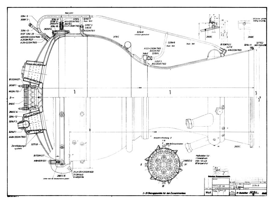
This diagram has sections of the burner cups and main fuel valve receptacle and shows the upper and lower "head chambers" or fuel manifolds at the forward end of the thrust chamber. It also shows one of the film cooling pipes. The drawing is dated 7.1.42, or 7 January 1942, and is drawing no. 3294 B.
Click image for a 1456x1080 pixel version of this image in a new window or
click here for a 7828x5808
pixel version of this image in a new window.
From the green "A-4 Details" binder in the archives of the U.S. Space &
Rocket Center.
Scan and restoration by heroicrelics.
Here is a similar drawing and dating to a slightly later period, 22 July 1942. It is drawing no. 4523 B:
Click image for a 1475x1080 pixel version of this image in a new window or
click here for a 7359x5390
pixel version of this image in a new window.
Located in the Dannenberg collection,
Dept. of Archives/Special
Collections, M. Louis Salmon Library, University of Alabama in
Huntsville.
Scan and restoration by heroicrelics.
Google's translator tells me that "Ansicht in Richtung" "View in the direction" (so "Ansicht in Richtung Y" would be "View in the Y direction"). Also, Google believes that "Lage der Bohrungen für Zusammenbau beachten" (in the small inset drawing near the lower right) means "Note location of boreholes for assembly."
The diagram had the following text. Tracy Dungan tells me that this text was not part of the original drawing, but was added by the Germans in the United States after the war.
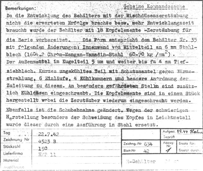
Text accompanying drawing.
Scan by heroicrelics.
Secret Command Matter
Remarks:
Since the development of the combustion chamber with mixing nozzle atomization did not produce the expected results and needed more development time, the combustion chamber with 18 burner cups was prepared for the series.
The form is compliant with the combustion chamber No. 35 with the following changes: inner skin of the middle section of 6 mm steel plate (1604.2 chrome-manganese-vanadium steel 60-70 kg/mm2).
The outer skin of the sphere part has 5 mm and continue to fm 4 mm deep drawing steelplates.
Non-cooled short part with protective coat against heat radiation. 6 inlets, 4 cooling chambers and better arrangement of the supply lines to them. At high-risk places additional cooling nozzles are screwed in. The burner cap elements are forged out of one piece with screwed-in feed nozzles. Also the thrustframe-connection is changed
Because of the difficult welding of light alloy the material of the combustion chamber head was changed to steel.
Translation courtesy Tracy Dungan, of www.v2rocket.com.
It appears to be dated 22 July 1942 ("Tag: 22.7.42"), but it also appears to be dated 9 September 1944 ("Aufgest. 9.9.44"). I know that "Tag" is simply "day" or "date", but I was unable to determine what the "Aufgest." abbreviation means.
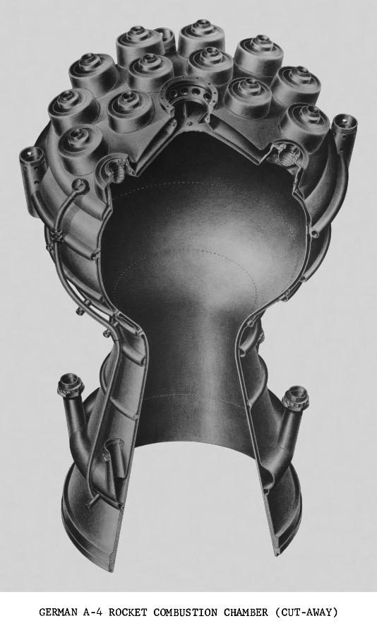
The combustion chamber featured a double-walled construction to facilitate regenerative cooling. Fuel (a 75% ethanol/water mixture) enters the area between the combustion chamber walls via six alcohol inlets located near the exit plane and makes its way up to top of the combustion chamber, through the main fuel valve, and finally to the burner cups at the top of the engine.
Even with the water added to the fuel, combustion temperatures were high enough to cause burn-throughs of the inner wall. To combat this, regenerative cooling was augmented by film cooling, provided by four rows of holes which were drilled through the inner combustion chamber wall. Three rows were located in the spherical combustion chamber, with one just aft of the burner cups and two near the throat. Another row was located in the nozzle, near the alcohol inlets. (The upper-most row of holes is not visible in the diagram below; see drawing 4523 B above for the locations of the film-cooling holes.) Four film cooling pipes carried fuel from the forward end of the combustion chamber to each of the film cooling manifolds.
Click image for a 1034x1734 pixel version of this image in a new window or
click here for a 3988x6688
pixel version of this image in a new window.
A composite featuring the combustion chamber cutaway from the green "A-4
Details" binder in the archives of the U.S. Space &
Rocket Center and page 31 of the from Technical Data on the
Development of the A4/V-2 in the private collection of Dave Christensen.
Also available from the NASA Technical Reports
Server; alternate
link.
Scan, clean-up, and composite by heroicrelics.
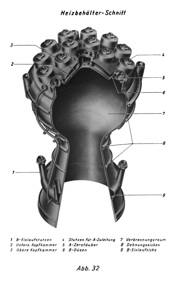
The combustion chamber drawing above formed the basis of additional diagrams. Here's one with callouts:
Click image for a 1091x1734 pixel version of this image in a new window or
click here for a 5140x8173
pixel version of this image in a new window.
A composite featuring a scan of the combustion chamber cutaway and a scan of
the captions from another diagram, both located in the green "A-4
Details" binder at the archives of the U.S. Space &
Rocket Center.
Original diagram is from page 101 of Das
Gerät A4, Baureihe B: Gerätbeschreibung vom 1.2.45 [direct
link to 29 megabyte PDF] (The Missile A-4, Series B: Description of
Missile as of Jan. 2, 1945).
Scan, reconstruction, and composite by heroicrelics.
Callouts on this "Heizbehälter - Schnitt" ("Combustion Chamber - Section") diagram include
- B-Einlaufstutzen
- Unterer Kopfraum
- Oberer Kopfraum
- Stutzen für A-Zuleitung
- A-Zerstäuber
- B-Düsen
- Verbrennungsraum
- Dehnungssicken
- B-Einlaufsicke
In English,
- Alcohol inlet stem
- Lower head chamber (lower section of fuel manifold)
- Upper head chamber (primary fuel manifold)
- Fitting for oxygen supply line
- Oxygen atomizer
- Fuel nozzle
- Combustion chamber
- (Thermal) expansion fold
- Alcohol inlet fold (alcohol inlet manifold)
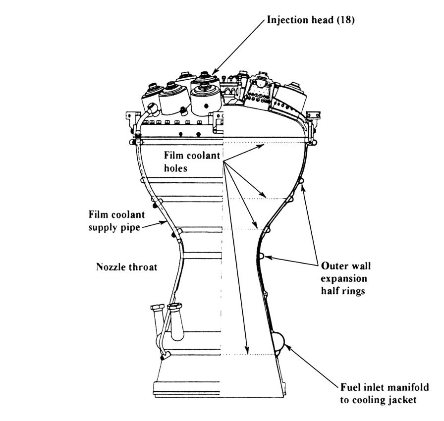
This cutaway shows the four rows of film cooling holes, the corresponding manifolds on the exterior of the combustion chamber, and the film coolant supply pipe:
Click image for a 2176x2488 pixel version of this image in a new window.
Adapted from page 747 of History of Liquid
Propellant Rocket Engines.
Scan, cleanup, and adaptation by heroicrelics.
Thanks to Dr. Dieter M. Zube for translation assistance.

