V-2 Rocket Engine Burner Cups
The V-2 was equipped with history's first large production rocket engine. While it was a "production" engine in the sense that it was mass-produced, the engineers (as is often the case) had additional changes they wished to make to the engine before they were willing to call it "done."
On of these changes relates to the method of injecting propellants into the combustion chamber: There was experimental work on a version of the engine with a flat-faced injector to replace the burner cups used to inject propellants into the production engine's combustion chamber. That version of the engine never made it to production and never flew.
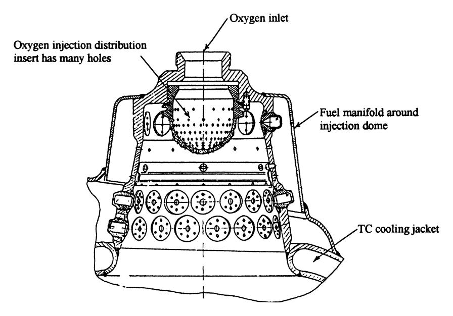
The production version of the V-2 engine was equipped with 18 burner cups. Each burner cup had three rows of fuel nozzles, two rows near the bottom and another row around the top; each burner cup also had a number of simple holes drilled through the its wall to admit additional fuel. At the center top of each burner cup was an oxygen atomizer. The propellants swirled and mixed in the burner cup, preheating before entering the combustion chamber proper.
Click image for a 2513x1757 pixel version of this image in a new window.
From page 593 of History of Liquid
Propellant Rocket Engines.
Scan and cleanup by heroicrelics.
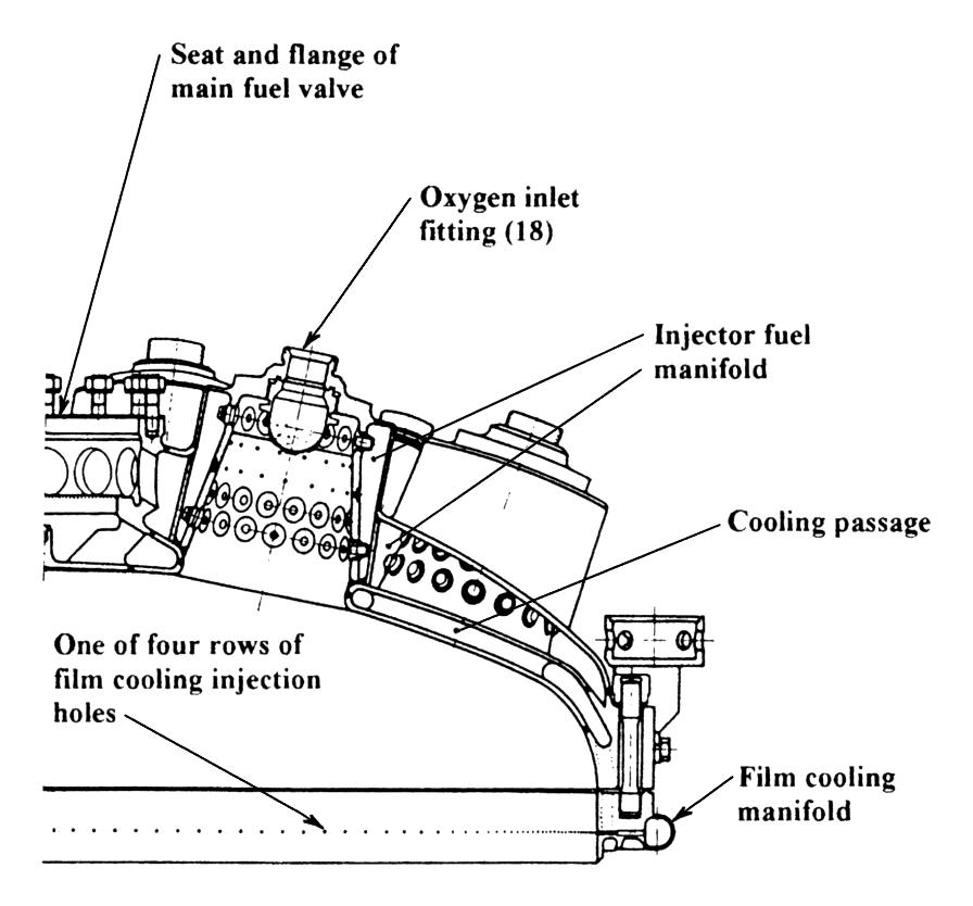
The burner cups were arranged in two concentric circles, the outer with twelve burner cups and the inner with six.
In the very center of the top of the combustion chamber, inside the inner ring of burner cups, was the engine's main fuel valve. While the body of the thrust chamber was of a dual-wall construction (circulating fuel between the walls for regenerative cooling), the top of the combustion chamber had three walls, forming the lower and upper "head chambers" or fuel manifolds: The regenerative cooling fuel arrived in the lower manifold, between the inner and middle walls. Prior to engine ignition, the main fuel valve directed this fuel from the lower manifold back to the turbopump inlet via a circulation line. At ignition, the fuel valve actuated, admitting fuel into the upper manifold, filling the area between the walls of the burner cups, and spraying it into the burner cups via the fuel nozzles and jet holes.
Click image for a 1756x2284 pixel version of this image in a new window.
Adapted from page 747 of History of Liquid
Propellant Rocket Engines.
Scan, cleanup, and adaptation by heroicrelics.
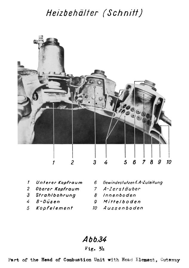
Here is a more detailed cut-away, taken from German technical documentation:
Click image for a 2242x3173 pixel version of this image in a new window.
From page 105b of Das
Gerät A4, Baureihe B: Gerätbeschreibung vom 1.2.45 [direct
link to 29 megabyte PDF] (The Missile A-4, Series B: Description of
Missile as of Jan. 2, 1945). This particular scan from an ABMA
microfiche, located in the Dannenberg collection, Dept. of Archives/Special
Collections, M. Louis Salmon Library, University of Alabama in
Huntsville.
Scan and cleanup by heroicrelics.
Callouts on this "Heizbehälter (Schnitt)" ("Combustion Chamber (Section)") diagram include
- Unterer Kopfraum
- Oberer Kopfraum
- Strahlbohrung
- B-Düsen
- Kopfelement
- Gewindestutzen f. A-Zuleitung
- A-Zerstäuber
- Innenboden
- Mittelboden
- Aussenboden
In English,
- Lower head chamber (lower section of fuel manifold)
- Upper head chamber (primary fuel manifold)
- Jet hole (boundary layer cooling hole)
- Fuel nozzle
- Head element (burner cup or pre-burner)
- Threaded fitting for oxygen supply line
- Oxygen atomizer
- Inner wall
- Middle wall
- Outer wall
Thanks to Dr. Dieter M. Zube for translation assistance.


