
Handling, Transporting, and Erection Instructions
Saturn S-1 Stage, SA-1
I've scanned, cleaned up, PDFed, and OCRed an early Marshall Space Flight Center manual entitled Handling, Transporting, and Erection Instructions Saturn S-1 Stage, SA-1 (EP-141). Dated 1 May 1961, this manual documents handling procedures for the Saturn I Block I first (S-I) stage at both the Static Test Tower and at Cape Canaveral with detailed, step-by-step instructions and many illustrations (including several fold-out pages). It also contains a "complete manual" for the Saturn S-I Transporter (including instructions for changing a flat tire), and each page is adorned with a rather unusual Saturn logo:

The manual's complete section introductions, tables of contents, and lists of illustrations are reproduced below.
For those interested in how a Saturn I (albeit the Block II version) was actually launched, refer to my Saturn I Countdown Manual Volume II, SA-7.
Proceed to download links.
Here are some highlights from the manual:

Excerpts:
| Introduction | Chapters 1 & 2 |
| Chapter 3 | |
| Table of Contents | Chapters 1 & 2 |
| Chapter 3 | |
| List of Illustrations | Chapters 1 & 2 |
| Chapter 3 |
Handling, Transporting, and Erection Instructions Saturn S-1 Stage, SA-1 (EP-141)
INTRODUCTIONThis manual provides the necessary instructions for transporting, handling, and erecting the Saturn S-I Booster, effectivity SA-1 and is divided into three chapters. Chapter I contains instructions at the static test tower . Chapter II contains instructions at the Cape Canaveral firing site . Chapter III contains operating instructions for the Saturn S-I Transporter.
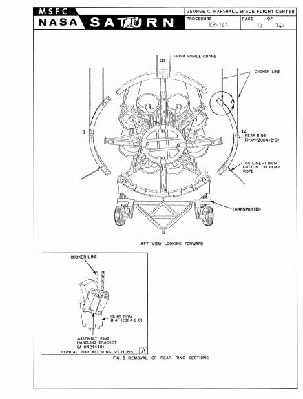
Chapter I consists of step-by-step procedures for removing the rear ring sections, positioning and erecting the Booster in the static test tower, preservation of tooling, positioning the Booster on the transporter, and reassembly of the rear ring sections to the Booster after static test firing.
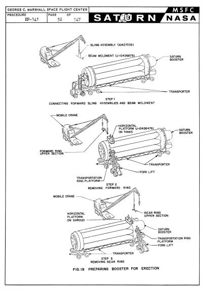
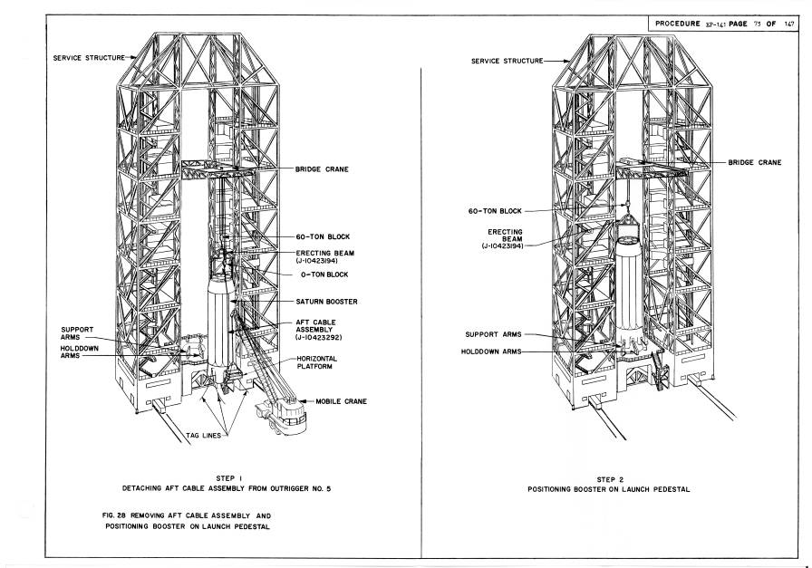
Chapter II consists of step-by-step procedures for removing the forward and rear ring sections, positioning and erecting the Booster from the launch pedestal, and preservation of tooling for shipping.
A complete manual containing general instructions for the Saturn S-I Transporter and including a separate Table of Contents, List of Illustrations, and Introduction is inserted in this manual as Chapter III.
Equipment essential to proper handling of the Booster at the static test tower and at the Cape Canaveral firing site includes the following: transporter, towing tractor, gantry crane, mobile crane, fork lift , horizontal and transportation ring platforms. Special hardware assures safe and efficient handling of the Booster during removal and erection.
This publication is a combined effort of the M-LOD, M-TEST, and M-F&AE Divisions.
TABLE OF CONTENTS
Paragraph                                                               Page
LIST OF ILLUSTRATIONS . . . . . . . . . . . . . . . . . . . . . . . . . .  3
INTRODUCTION  . . . . . . . . . . . . . . . . . . . . . . . . . . . . . .  5
CHAPTER I TRANSPORTATION, HANDLING, AND ERECTION AT STATIC TEST TOWER . .  7
1. PREPARING BOOSTER FOR ERECTION . . . . . . . . . . . . . . . . . . . .  7
1.1 Positioning Transporter (J-AF-12004)  . . . . . . . . . . . . . . . .  7
1.2 Installing Bumper Assembly (D-10426438), Two Bumpers (D-10426434),
      and Two Cable Assemblies (J-10424771) . . . . . . . . . . . . . . .  7
1.3 Removal Procedure Rear Ring Sections (J-AF-12004-2-0) . . . . . . . . 11
2. ERECTING BOOSTER . . . . . . . . . . . . . . . . . . . . . . . . . . . 20
2.1 Positioning Transporter and Attaching Erection Cables . . . . . . . . 20
2.2 Removing Booster from Transporter and Positioning on Tower
      Thrust Ring . . . . . . . . . . . . . . . . . . . . . . . . . . . . 28
3. REMOVING BOOSTER FROM TEST TOWER . . . . . . . . . . . . . . . . . . . 35
3.1 Preparing Booster for Removal . . . . . . . . . . . . . . . . . . . . 35
3.2 Removing Booster from Tower Thrust Ring and Positioning on
      Transporter . . . . . . . . . . . . . . . . . . . . . . . . . . . . 37
3.3 Installation Procedure Rear Ring Sections (J-AF-12004-2-0)  . . . . . 40
3.4 Removing Bumper Assembly (D-10426438), Two Bumpers (D-10426434)
      and Two Cable Assemblies (J-10424771) . . . . . . . . . . . . . . . 44

CHAPTER II TRANSPORTATION, HANDLING, AND ERECTION AT CAPE CANAVERAL . . . 47
1. PREPARING BOOSTER FOR ERECTION . . . . . . . . . . . . . . . . . . . . 47
1.1 Preparing Service Structure for Erection  . . . . . . . . . . . . . . 47
1.2 Positioning Transporter (J-AF-12004)  . . . . . . . . . . . . . . . . 47
1.3 Installing Beam Weldment (J-10426675) and Forward Sling Assemblies
      (J-10426668)  . . . . . . . . . . . . . . . . . . . . . . . . . . . 51
1.4 Removal Procedure Forward Ring Sections (J-AF-12004-3-0)  . . . . . . 54
1.5 Removal Procedure Rear Ring Sect ions (J-AF-12004-2-0)  . . . . . . . 60
2. ERECTING BOOSTER . . . . . . . . . . . . . . . . . . . . . . . . . . . 64
2.1 Positioning Transporter and Attaching Cables  . . . . . . . . . . . . 64
2.2 Removing Booster from Transporter and Positioning on Launch Pedestal  72
3. REMOVING BOOSTER FROM LAUNCH PEDESTAL  . . . . . . . . . . . . . . . . 79
4. REMOVING RING SECTIONS WITH FIN I IDENTIFICATION AND PRESERVING ALL
     RING DETAILS AND ATTACHING HARDWARE  . . . . . . . . . . . . . . . . 80
4.1 Removing Forward and Rear Ring Sections with Fin I Identification
      from Transporter  . . . . . . . . . . . . . . . . . . . . . . . . . 80
4.2 Preserving Forward and Rear Ring Details and Attaching Hardware . . . 82

CHAPTER III GENERAL INSTRUCTIONS FOR THE S-I TRANSPORTER  . . . . . . . . 83
LIST OF ILLUSTRATIONS
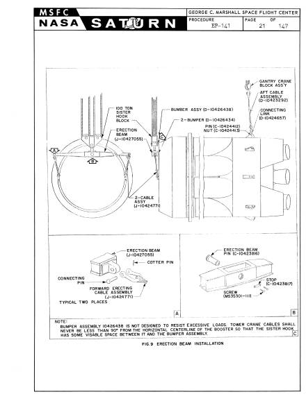
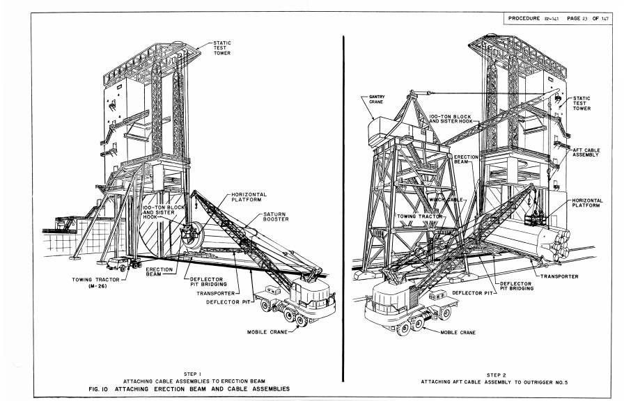
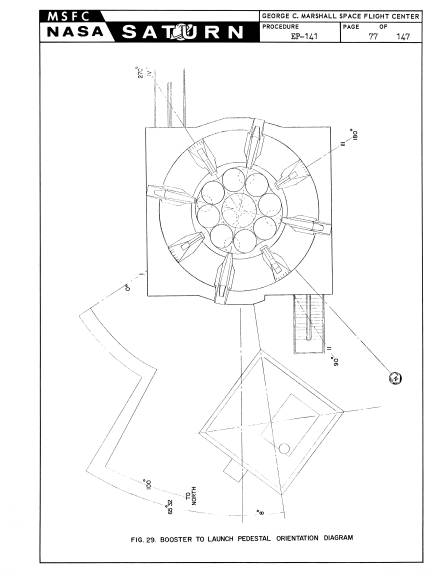
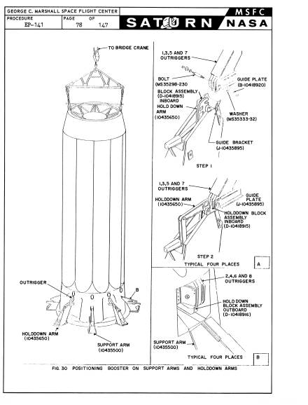
Figure                            Title                            Page
 1. Positioning Equipment at Static Test Tower . . . . . . . . . . .  8
 2. Removing Doors and Plates  . . . . . . . . . . . . . . . . . . .  9
 3. Installing Bumpers and Cable Assemblies  . . . . . . . . . . . . 10
 4. Positioning Horizontal Platform and Personnel  . . . . . . . . . 12
 5. Removal of Rear Ring Sections (J-AF-12004-2-0) . . . . . . . . . 13
 6. Rear Ring Section Attaching Points . . . . . . . . . . . . . . . 14
 7. Removal of Rear Ring Section at Outrigger No. 2  . . . . . . . . 18
 8. Identification of Fin Line and Outrigger Numbers . . . . . . . . 19
 9. Erection Beam Installation . . . . . . . . . . . . . . . . . . . 21
10. Attaching Erection Beam and Cable Assemblies . . . . . . . . . . 23
11. Connecting Aft Cable Assembly  . . . . . . . . . . . . . . . . . 25
12. Forward Support Clamps . . . . . . . . . . . . . . . . . . . . . 27
13. Lifting Booster off Transporter  . . . . . . . . . . . . . . . . 29
14. Booster Stabilization Preparatory to Lifting off Transporter . . 31
15. Booster in Vertical Position . . . . . . . . . . . . . . . . . . 33
16. Positioning Booster on Support Brackets  . . . . . . . . . . . . 36
17. Preparing Service Structure for Erection . . . . . . . . . . . . 48
18. Positioning Equipment at Firing Site . . . . . . . . . . . . . . 49
19. Preparing Booster for Erection . . . . . . . . . . . . . . . . . 52
20. Installation of Beam Weldment and Forward Sling Assemblies . . . 53
21. Removing Forward Ring Sections (J-AF-12004-3-O)  . . . . . . . . 55
22. Forward Ring Section Attaching Points  . . . . . . . . . . . . . 56
23. Forward Ring Section Removal Procedures  . . . . . . . . . . . . 57
24. Attaching Aft and Forward Sling Assemblies . . . . . . . . . . . 65
25. Connecting Erecting Beam and Forward Sling Assemblies  . . . . . 68
26. Lifting Booster off Transporter  . . . . . . . . . . . . . . . . 69
27. S-I Stage Center-of-Gravity Diagram  . . . . . . . . . . . . . . 71
28. Removing Aft Cable Assembly and Positioning Booster on Launch
      Pedestal . . . . . . . . . . . . . . . . . . . . . . . . . . . 75
29. Booster-to-Launch Pedestal Orientation Diagram . . . . . . . . . 77
30. Positioning Booster on Support Arms and Holddown Arms  . . . . . 78
31. Rear Ring Support Clamps . . . . . . . . . . . . . . . . . . . . 81
CHAPTER III
GENERAL INSTRUCTIONS
FOR THE
SATURN S-I TRANSPORTER
INTRODUCTIONThe primary purpose of this chapter is to provide the necessary information for operation of the Saturn S-I transporter. This chapter is presented in seven main paragraphs. Paragraph 1. contains a description of the transporter and leading particulars of its major components. Paragraph 2. presents operating procedures necessary for complete operation and control of the transporter. Paragraph 3. contains installation and removal procedures for installing the dollies to or removing the dollies from the assembly fixture. Paragraph 4. gives instructions for shipment of entire transporter with cargo by barge. Paragraph 5. contains information for operation of portable storage jacks used to support fixtures and cargo if stored on a hardstand area. Paragraph 6. contains information pertaining to the preparation for shipment of a complete dolly by either motor freight or railroad, and paragraph 7. contains instructions for shipping the fixture assembly by commercial means.
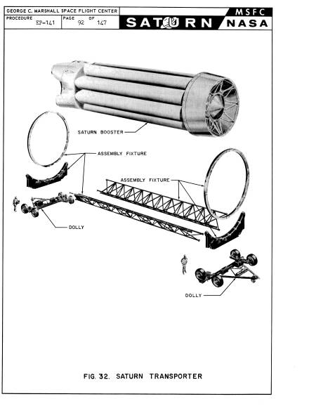
The transporter is specifically designed to transport the Saturn booster from one location to another and provide complete maneuverability at each location. The transporter consists of three major assemblies and is towed by a prime mover. Steering of the transporter is accomplished by two operators, one seated on each dolly. Unless otherwise stated, the terms left-hand and right-hand appearing in this chapter refer to the left and right of a person seated in the prime mover facing forward.
TABLE OF CONTENTS
Paragraph                                                            Page
LIST OF ILLUSTRATIONS . . . . . . . . . . . . . . . . . . . . . . . .  87
INTRODUCTION  . . . . . . . . . . . . . . . . . . . . . . . . . . . .  89
1. DESCRIPTION AND LEADING PARTICULARS  . . . . . . . . . . . . . . .  91
1.1 Description . . . . . . . . . . . . . . . . . . . . . . . . . . .  91
1.2 Leading Particulars . . . . . . . . . . . . . . . . . . . . . . . 103
2. OPERATING PROCEDURES . . . . . . . . . . . . . . . . . . . . . . . 107
2.1 General . . . . . . . . . . . . . . . . . . . . . . . . . . . . . 107
2.2 Preoperational Check  . . . . . . . . . . . . . . . . . . . . . . 107
2.3 Starting and Stopping Power Unit and Lamp Test  . . . . . . . . . 111
2.4 Locking and Unlocking Wheels  . . . . . . . . . . . . . . . . . . 111
2.5 Steering the Dolly  . . . . . . . . . . . . . . . . . . . . . . . 112
2.6 Operating the Brakes  . . . . . . . . . . . . . . . . . . . . . . 113
2.7 Tire Change Procedure . . . . . . . . . . . . . . . . . . . . . . 113
3. INSTALLATION AND REMOVAL PROCEDURES  . . . . . . . . . . . . . . . 116
3.1 Installation  . . . . . . . . . . . . . . . . . . . . . . . . . . 116
3.2 Removal . . . . . . . . . . . . . . . . . . . . . . . . . . . . . 118
4. SHIPMENT BY BARGE  . . . . . . . . . . . . . . . . . . . . . . . . 118
4.1 Description . . . . . . . . . . . . . . . . . . . . . . . . . . . 118
4.2 Loading at MSFC . . . . . . . . . . . . . . . . . . . . . . . . . 120
4.3 Tie-Down Arrangement  . . . . . . . . . . . . . . . . . . . . . . 120
4.4 Unloading at AMR  . . . . . . . . . . . . . . . . . . . . . . . . 123
5. SATURN S-I PORTABLE JACKS  . . . . . . . . . . . . . . . . . . . . 124
5.1 Description . . . . . . . . . . . . . . . . . . . . . . . . . . . 124
5.2 Work Area Requirements  . . . . . . . . . . . . . . . . . . . . . 124
5.3 Power Requirements  . . . . . . . . . . . . . . . . . . . . . . . 124
5.4 Positioning Booster . . . . . . . . . . . . . . . . . . . . . . . 124
5.5 Electrical and Mechanical Checkout  . . . . . . . . . . . . . . . 128
5.6 Positioning Jacks under Jack Pad  . . . . . . . . . . . . . . . . 128
5.7 Lifting . . . . . . . . . . . . . . . . . . . . . . . . . . . . . 131
5.8 Storage . . . . . . . . . . . . . . . . . . . . . . . . . . . . . 131
5.9 To Replace Cradles on Transporter . . . . . . . . . . . . . . . . 131
5.10 Emergency Use:  Dolly Repairs, Tire Change, Etc. . . . . . . . . 131
5.11 Lubrication Instructions . . . . . . . . . . . . . . . . . . . . 133
6. PREPARATION OF DOLLIES FOR SHIPMENT BY COMMERCIAL CARRIER  . . . . 133
6.1 General . . . . . . . . . . . . . . . . . . . . . . . . . . . . . 133
6.2 Loading and Tie-Down Procedures for Operator's Seat, Detachable
      Drawbar, and Dolly  . . . . . . . . . . . . . . . . . . . . . . 133
7. PREPARATION OF FIXTURE FOR SHIPMENT BY COMMERCIAL CARRIER  . . . . 139
7.1 General . . . . . . . . . . . . . . . . . . . . . . . . . . . . . 139
7.2 Preservation of Assembly Fixture  . . . . . . . . . . . . . . . . 139
LIST OF ILLUSTRATIONS
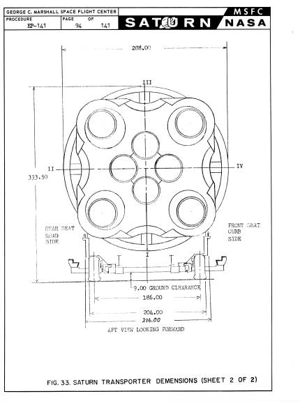
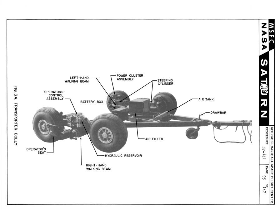
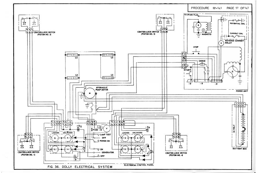
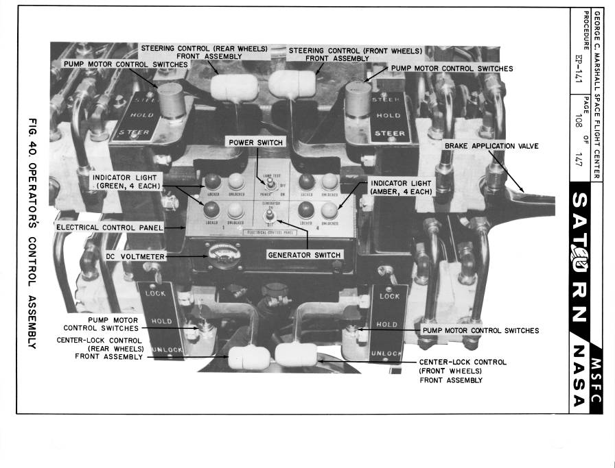
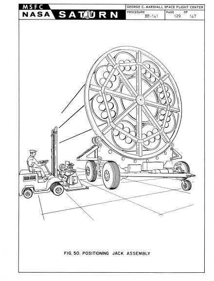
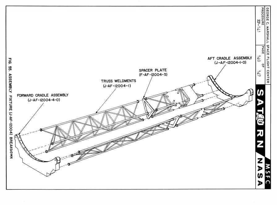
Figure                             Title                             Page
32    Saturn Transporter  . . . . . . . . . . . . . . . . . . . . . .  92
33    Saturn Transporter Dimensions . . . . . . . . . . . . . . . . .  93
34    Transporter Dolly . . . . . . . . . . . . . . . . . . . . . . .  95
35    Drawbar Extension . . . . . . . . . . . . . . . . . . . . . . .  96
36    Dolly Electrical System . . . . . . . . . . . . . . . . . . . .  97
37    Front Dolly Steering System . . . . . . . . . . . . . . . . . .  99
38    Rear Dolly Steering System  . . . . . . . . . . . . . . . . . . 101
39    Air over Hydraulic Brake System . . . . . . . . . . . . . . . . 105
40    Operator's Control Assembly . . . . . . . . . . . . . . . . . . 108
41    Lubrication Chart . . . . . . . . . . . . . . . . . . . . . . . 109
42    Jacking for Wheel Removal . . . . . . . . . . . . . . . . . . . 114
43    Wheel Removal and Installation  . . . . . . . . . . . . . . . . 115
44    Removing and Installing Dolly to Assembly Fixture . . . . . . . 117
45    Attaching Fixture to Dolly  . . . . . . . . . . . . . . . . . . 119
46    Tie Down Arrangement S-1 to Barge . . . . . . . . . . . . . . . 121
47    Portable Jack Assembly  . . . . . . . . . . . . . . . . . . . . 125
48    Jack Positioning and Cable Inter-Connect Diagram  . . . . . . . 126
49    Attaching Jack Pad Assembly . . . . . . . . . . . . . . . . . . 127
50    Positioning Jack Assembly . . . . . . . . . . . . . . . . . . . 129
51    Jack Assembly under Jack Pad  . . . . . . . . . . . . . . . . . 130
52    Fixture Assembly Supported by Jack Assemblies . . . . . . . . . 132
53    Tie-Down Procedures . . . . . . . . . . . . . . . . . . . . . . 134
54    Installing Operator's Seat on Drawbar . . . . . . . . . . . . . 137
55    Assembly Fixture AF-12004 Breakdown . . . . . . . . . . . . . . 140
56    Packaging Truss Weldments and Miscellaneous Hardware  . . . . . 141
57    Packaging Aft and Forward Cradles . . . . . . . . . . . . . . . 143
58    Packaging Ring Sections . . . . . . . . . . . . . . . . . . . . 145
Download Links
I've prepared three PDFs:
- A web-resolution PDF for the casual visitor; 23 megabytes. View now.
- A 300-dpi version for serious study; 61 megabytes. Download now.
- A 600-dpi version for those of you out there with really beefy PCs and like to zoom in to 800%, or want to go to your local copy shop and print up a copy of your own, or even want to blow some drawings up to the size of your wall; 334 megabytes. Download now.