
Mercury Space Suit
The pressure suit used in the Mercury program was developed from the U.S. Navy MK-IV full pressure suit manufactured by the B.F. Goodrich Co. This basic suit was selected by NASA in July 1959 for use in Project Mercury after an extensive evaluation program. Many design changes were made to the suit during the course of the Mercury program.

Astronaut L. Gordon Cooper in his Project Mercury space suit.
Click image to open its page on Wikimedia
Commons in a new window.
The full pressure suit consisted five basic components, the suit torso, helmet, gloves, boots, and undergarment.
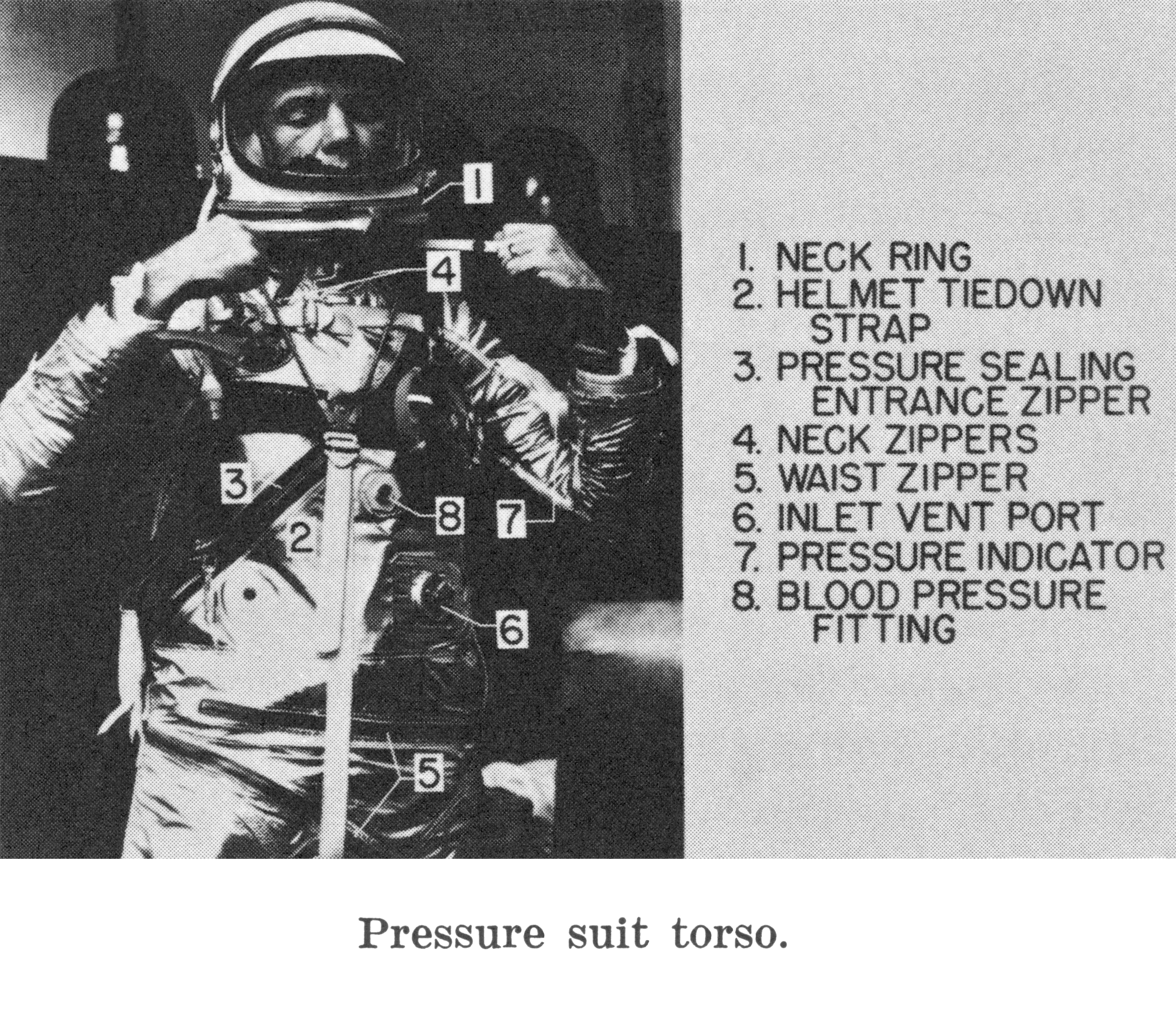
Pressure Suit Torso
The suit torso was a closely-fitted coverall tailored for each of the astronauts. It covered all of the body except for the head and hands. The torso section was of two-ply construction: an inner gas-retention ply of neoprene and neoprene-coated nylon fabric and an outer ply of heat-reflective, aluminized nylon fabric. The helmet attached to the torso section via a rigid neck ring. A tie-down strap was provided on the neck ring to prevent the helmet from rising when the suit was pressurized. Straps were also provided on the torso section for minor sizing adjustments of the leg and arm length and circumferences and to prevent the suit from ballooning when pressurized.
Click image for a 3578x3076 pixel version of this image in a new window.
From page 34 of the Results of the First U.S. Manned Orbital Space
Flight, located in the heroicrelics library. Also available electronically
from the NASA Technical Reports
Server.
Scan and cleanup by heroicrelics.
This diagram has the following callouts:
- Neck Ring
- Helmet Tiedown Strap
- Pressure Sealing Entrance Zipper
- Neck Zippers
- Waist Zipper
- Inlet Vent Port
- Pressure Indicator
- Blood Pressure Fitting
Donning and doffing of the suit was provided through a pressure-sealing entrance zipper which extended diagonally across the front of the torso from the left shoulder down to the waist. Two frontal neck zippers and a circumferential waist zipper was also provided for ease in donning and doffing.
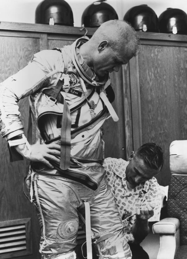
Astronaut John H. Glenn Jr. is assisted by Joe W. Schmitt as he suits up in
practice for the preparation of Mercury-Atlas 6 (MA-6) mission.
NASA photo S62-00246. Click image to open its page at the Internet Archive in a new window.
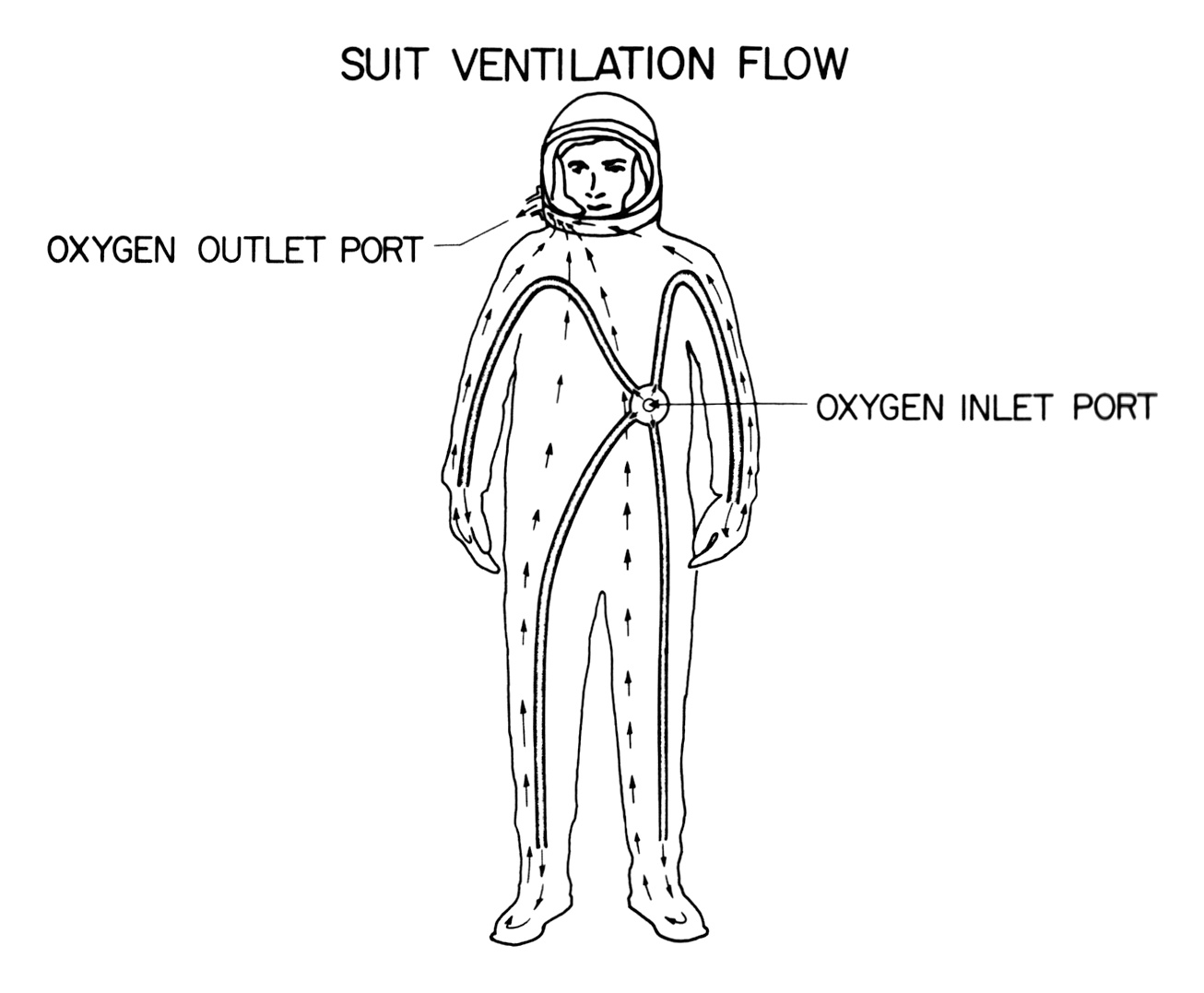
The pressure-suit ventilation system was an integral part of the torso section. A ventilation inlet port was located at a point just above the waist on the left side of the torso section. This inlet port was connect to a manifold inside the suit where vent tubes led to the body extremities. These tubes were constructed of a helical spring covered by a neoprene-coated nylon fabric that contained perforations at regular intervals. Body ventilation was provided by forcing oxygen from the environmental control system to the inlet and distributing the gas evenly over the body.
Click image for a 1306x1077 pixel version of this image in a new window.
From page 44 (p. 46 in the PDF) of the Conference on Medical Results of
the First U.S. Manned Suborbital Space Flight.
Extraction and cleanup by heroicrelics.
The suit torso section contained several items which were developed specifically for Project Mercury, including
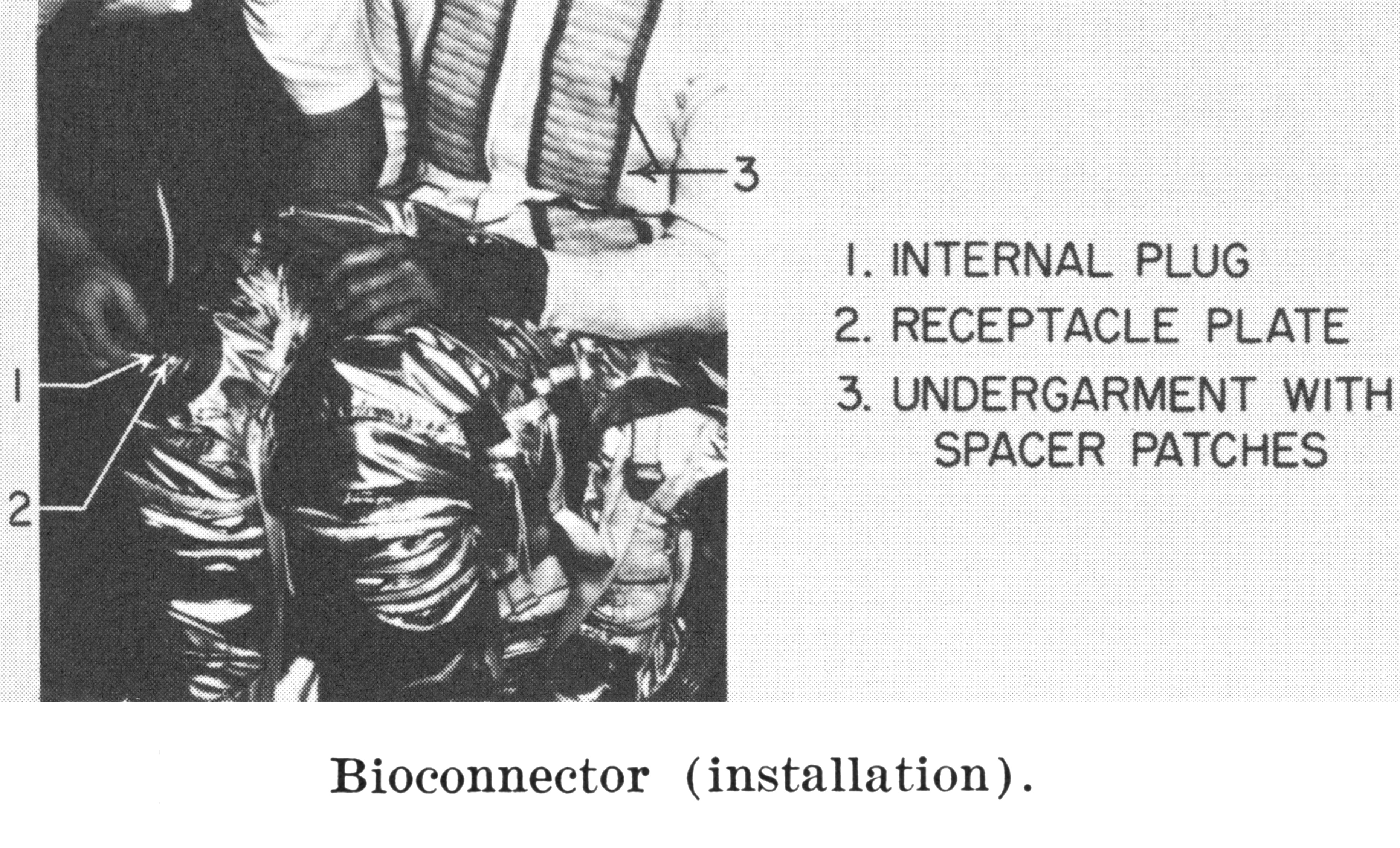
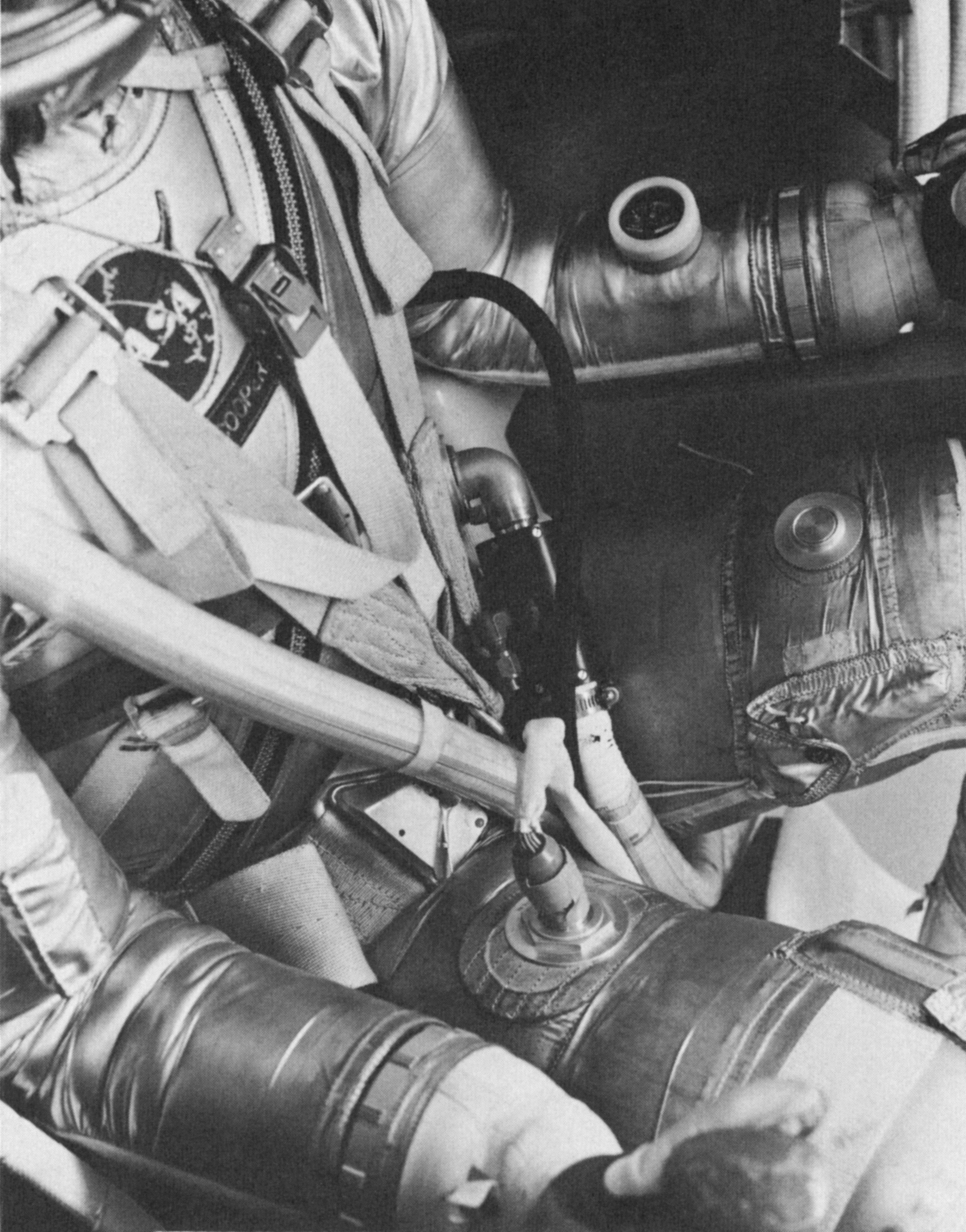
Bioconnector—The bioconnector provided a method for bringing medical data leads through the pressure suit. The bioconnector consisted of a multi-pin electrical plug to which the biosensors were permanently attached, a receptacle plate mounted to the suit torso section and an outside plug which was connected to the spacecraft instrumentation system. With this system, the biosensor harness was fabricated with the bioconnector as an assembly and no additional electrical connectors were introduced into the transducer system. In operation, the male internal plug was inserted inside the suit receptacle and locked into place. The internal plug protruded through the suit to allow the spacecraft plug to be attached.
Click image for a 3717x2251 pixel version of this image in a new window.
From page 35 of the Results of the First U.S. Manned Orbital Space
Flight, located in the heroicrelics library. Also available electronically
from the NASA Technical Reports
Server.
Scan and cleanup by heroicrelics.
This diagram has the following callouts:
- Internal Plug
- Receptacle Plate
- Undergarment with Spacer Patches
I believe that this is the only photo I've ever seen of the bioconnector attached to the spacecraft systems:
Click image for a 2158x2751 pixel version of this image in a new window.
From page 60 of the Mercury Project Summary Including Results of the Fourth
Manned Orbital Flight, May 15 and 16, 1963, located in the heroicrelics
library. Also available electronically from the NASA Technical Reports
Server.
Scan and cleanup by heroicrelics.
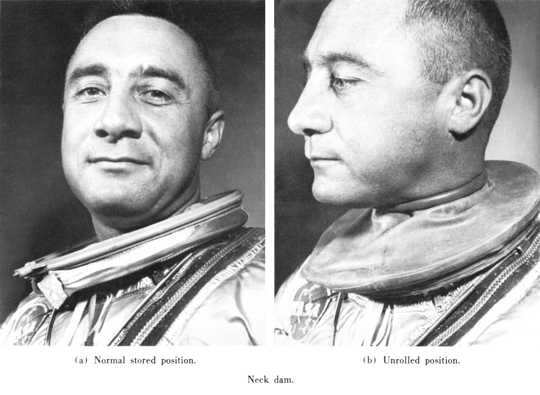
Neck Dam—A conical rubber neck dam was attached to the torso neck ring. The purpose of this neck dam was to prevent water from entering the suit in event of water egress with the helmet off. When preparing to egress the spacecraft, the astronaut would unfasten the helmet from the suit and roll up the neck dam. The rubber diaphragm was fastened on the exterior of the suit, below the helmet attaching ring. After the helmet was disconnected, the neck dam would be rolled around the ring and up around the neck, similar to a turtle-neck sweater, until it provided a seal around the neck.
Click image for a 1871x1367 pixel version of this image in a new window.
From page 54 (p. 59 in the PDF) of Results of the Second U.S.
Manned Suborbital Space Flight, July 21, 1961.
Extraction and cleanup by heroicrelics.
Strangely, this NTRS scan was a higher-quality reproduction than the version of
this photo in my physical copy of the Results of the First U.S. Manned
Orbital Space Flight.
Pressure Indicator—A wrist-mounted pressure indicator was worn on the left arm. It provided the astronaut a cross-check on his suit-pressure level. The indicator was calibrated from 3 to 6 psi.
Blood-Pressure Connector—A special fitting was provided on the suit torso to permit pressurization gas to be fed into the blood-pressure cuff. A hose leading from the cuff was attached to this connector during suit donning. After astronaut ingress into the spacecraft the pressurization source was attached to the connector on the outside of the suit.
Helmet
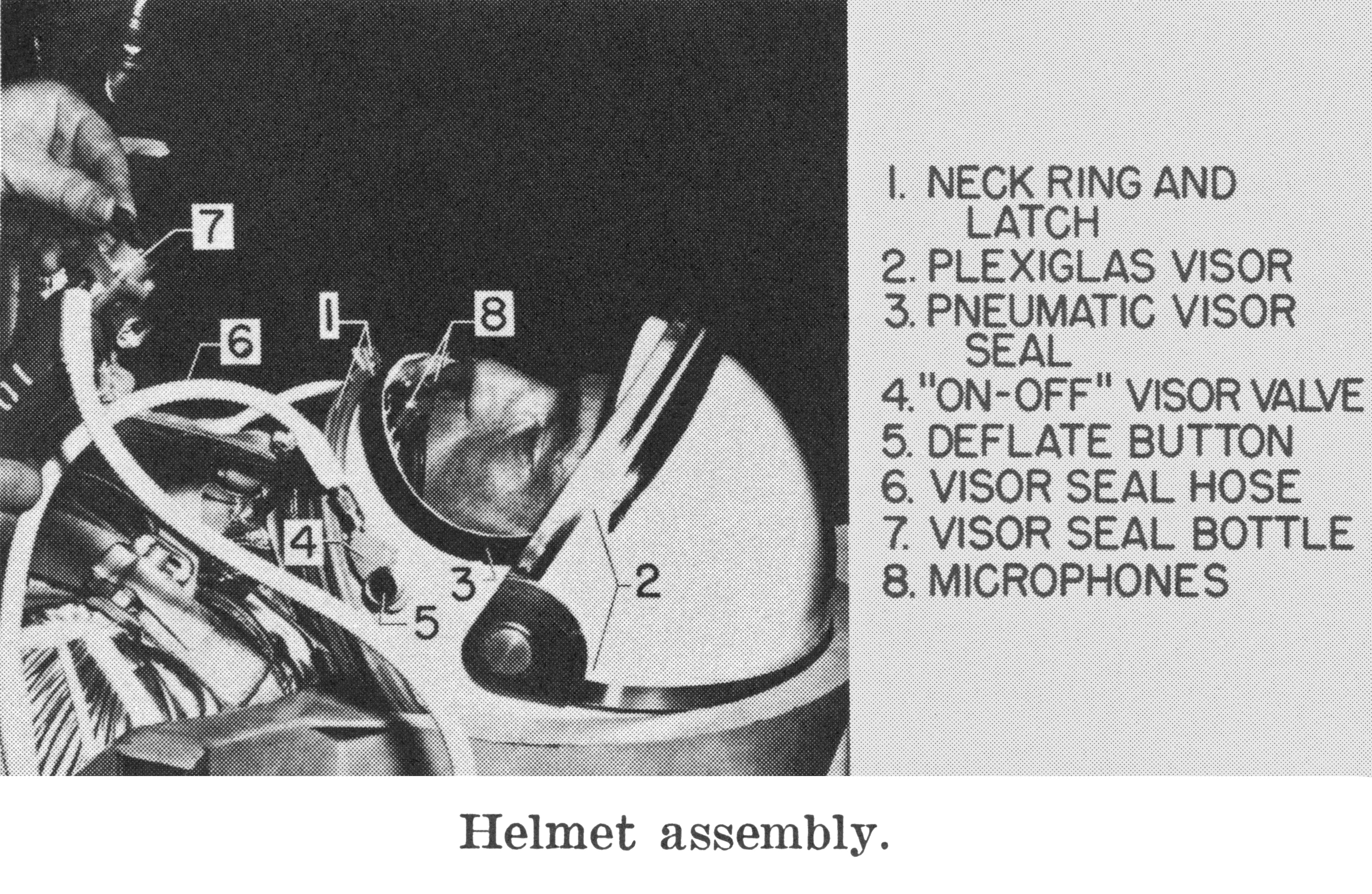
The helmet assembly consisted of a resinous, impregnated Fiberglas hard shell; an individually-molded crushable impact liner; a ventilation exhaust outlet; a visor sealing system; and a communications system.
Click image for a 3699x2410 pixel version of this image in a new window.
From page 36 of the Results of the First U.S. Manned Orbital Space
Flight, located in the heroicrelics library. Also available electronically
from the NASA Technical Reports
Server.
Scan and cleanup by heroicrelics.
This diagram has the following callouts:
- Neck Ring and Latch
- Plexiglas Visor
- Pneumatic Visor Seal
- "On-Off" Visor Valve
- Deflate Button
- Visor Seal Hose
- Visor Seal Bottle
- Microphones
The helmet's visor sealing system consisted of a pivoted Plexiglas visor, a pneumatic visor seal, and an on-off visor valve. Closing the visor actuated the valve and caused automatic inflation of the visor seal. The visor seal remained inflated until the deflation button on the valve was manually actuated by the astronaut. The valve had provision for attachment of the visor-seal gas-supply bottle hose.
The helmet communication system consisted of two independently-wired AIC-10 earphones with sound attenuation cups and two independently-wired AIC-10, newly-developed, dynamic, noise-cancelling microphones. The microphones were installed on tracks which allowed them to be moved back from the center of the helmet to permit eating and proper placement.
Gloves
The gloves attached to the suit torso at the lower forearm by means of a detent ball bearing lock. The gloves were specially developed for Project Mercury to provide the maximum comfort and mobility. Early centrifuge programs dictated the requirements for this development: Poor mobility in wrist action when the suit was pressurized caused an impairment in the use of the three-axis hand controller.
A pressure-sealing wrist bearing was incorporated to improve mobility in the yaw-control axis. The one-way stretch material on the back of the gloves improved mobility in the pitch and roll axes.
The gloves had curved fingers so that when pressurized the gloves assumed the contour of the hand controller. The glove, like the torso section, had a two-ply construction—the inner gas retention ply and an outer restraint ply. The inner ply was fabricated by dipping a mold of the astronaut's hand into Estane material. The outer ply was fabricated from one-way stretch nylon on the back of the hands and fingers and a neoprene material injected into a nylon fabric in the palm of the gloves to prevent slippage in turning knobs and so forth. Lacings were provided on the back of the glove to allow for minor adjustments. Two wrist restraint straps were provided to form break points and thereby improve pressurized glove mobility.
Miniature needle-like red finger lights were provided on the index and middle fingers of both gloves. Electrical power was supplied to the miniature lights by a battery pack and switch on the back of the gloves. These lights provide instrument panel and chart illumination before the astronaut is adapted to night vision.
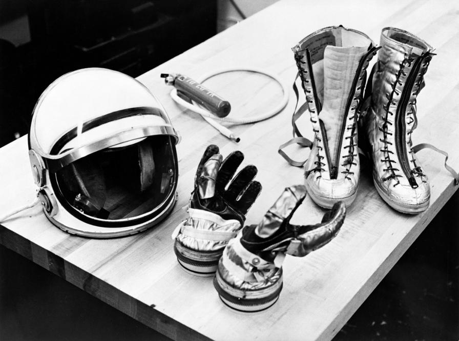
The Mercury spacesuit included gloves, boots and a helmet.
NASA photo S61-02733. Click image to open its page on NASA's Website in a new
window.
Boots
Lightweight, aluminized, nylon-fabric boots with tennis shoe-type soles were specially designed for the Mercury pressure suit. These boots resulted in substantial weight savings, provided a comfortable boot for flight, and a flexible friction sole which aided in egress from the spacecraft.
The boots served much the same purpose as any ordinary boot and were not part of the pressure garment. The suit's feet were an integral part of the torso's inner gas-retention layer. The boots served to provide abrasion protection and prevent ballooning when pressurized.
Undergarment
The undergarment was a one-piece, lightweight, cotton garment with long sleeves and legs. Thumb loops were provided at the sleeve ends to prevent material from riding up the arms during suit donning. Ventilation spacer patches of a trilock construction were provided on the outside of the undergarment to insure ventilation gas flow over certain critical areas of the body.
In the following photo, it would appear that the suit technician is preparing to install the bioconnector into the interior portion of the receptacle on the suit's leg; note the various wires leading to the connector. Also note, between Shepard's left hand and the suit tech's hand, what would appear to be a suit ventilation tube:
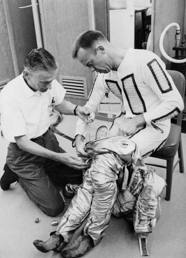
Astronaut Alan B. Shepard Jr. is being helped into the lower half of his
pressure suit for the Mercury-Redstone 3 (MR-3) flight, the first American
manned spaceflight.
NASA photo S61-02755. Click image to open its page on NASA's Hangar S During
Project Mercury repository in a new window.
Prior to and after astronaut donning of the pressure suit the complete assembly was pressurized and leak checked at 5 psig, and at 5 inches of water differential pressure.
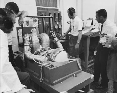
Astronaut Alan B. Shepard Jr. in flight couch for final check before insertion
into capsule for his Mercury-Redstone 3 (MR-3) flight.
NASA photo S61-02767. Click image to open its page at the NASA Image and Video Library in a new window.
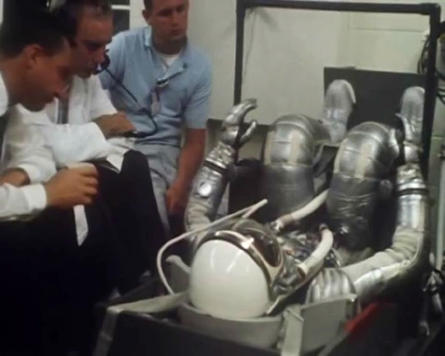
Alan Shepard's Project Mercury space suit undergoing leak/pressurization
test.
Click image to view the YouTube video Freedom 7 in a new
window.
Extraction and cleanup by heroicrelics.
During astronaut transfer from the suit dressing room to the launching pad, a lightweight, hand-carried, portable ventilator provided suit cooling.
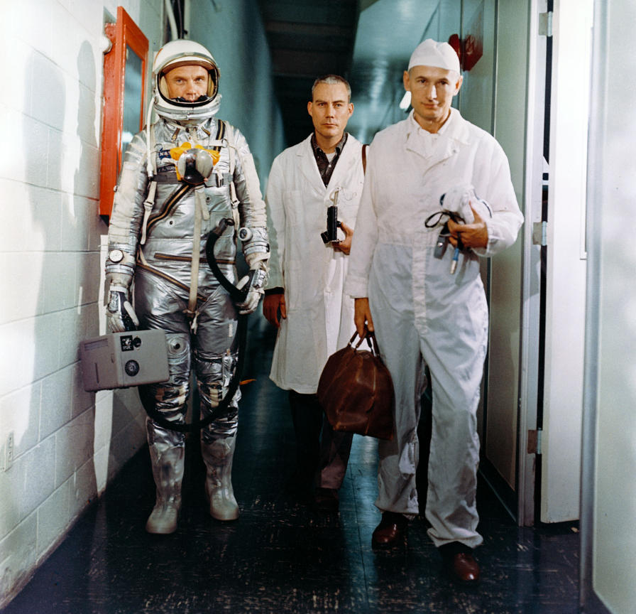
Astronaut John H. Glenn Jr., NASA flight surgeon William Douglas and equipment
specialist Joseph W. Schmidt leave crew quarters prior to the Mercury-Atlas 6
mission. Glenn is in his pressure suit and is carrying the portable ventilation
unit.
NASA photo S62-00330. Click image to open its page at the NASA Image and Video Library in a new window.
Constant communications were maintained with the astronaut during transfers via portable communications headsets carried by the astronaut insertion team.
For the Mercury flights, the pressure suit served as a flight suit, since the cabin pressure was maintained.
I was somewhat dismayed that I was unable to locate a labelled, overall diagram of the Project Mercury space suit, so I created one myself:
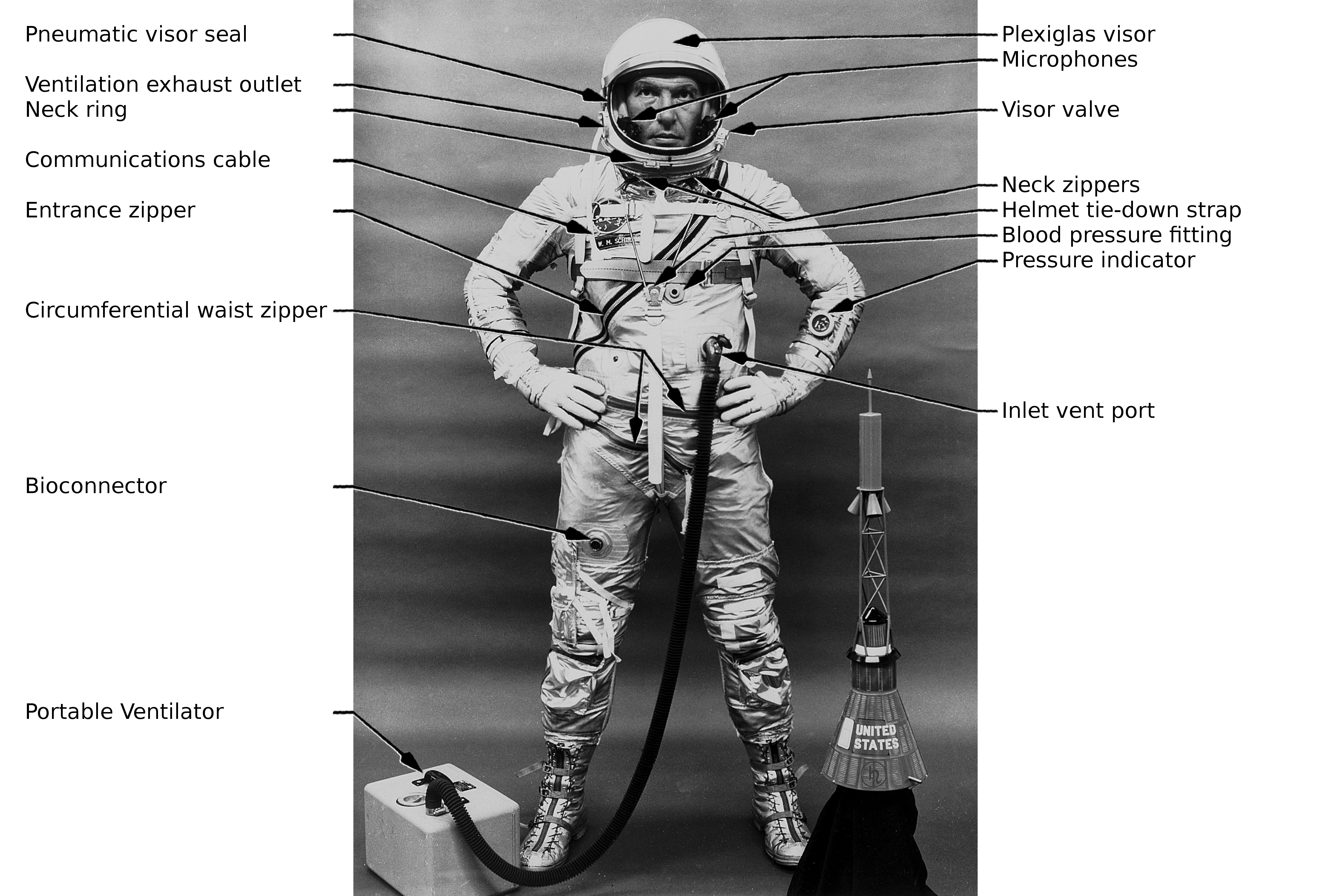
Click image for a 4456x3000 pixel version of this image in a new window.
Based on NASA photo MSFC-8892072.
Markup by heroicrelics.
This diagram has the following callouts:
- Pneumatic visor seal
- Ventilation exhaust outlet
- Neck ring
- Communications cable
- Entrance zipper
- Circumferential waist zipper
- Bioconnector
- Portable Ventilator
- Plexiglas visor
- Microphones
- Visor valve
- Neck zippers
- Helmet tie-down strap
- Blood pressure fitting
- Pressure indicator
- Inlet vent port
The bulk of the descriptive text was taken, largely verbatim, from the Results of the First U.S. Manned Orbital Space Flight.