Assembly Line Produces Rocket Engines
Thin nickel tubes, brazed with solder and held in place with thin steel bands, form the envelope for the United States' largest liquid propellant rocket—in production for Thor, Thor-Able, Atlas and Jupiter.
by Norman L. Baker
[heroicrelics: This is one of a series of four articles I've reproduced from issues of Missiles and Rockets magazine documenting Rocketdyne's engine production in Neosho, Missouri: July 7, 1958; July 21, 1958; October 20, 1958 (this article); and August 1, 1960.]
Neosho, Mo.—The Air Force lunar probe attempt of August 17 was started on its way by the first production rocket engine to roll from Rocketdyne-Neosho's assembly lines.
The largest single chamber unit in production in the United States, its status as a mass assembly item represents one of the most radical advancements in missile technology. The technique employed in fabrication is a unique approach to the weight/cooling problem that has plagued engineers for many years.
Although the Neosho engines are being produced for the Thor IRBM, similar construction is used on the booster and sustainer engines for the Atlas ICBM and the Army-developed Jupiter IRBM. Major differences in the engines are in the propellant feed system. Fabrication of the thrust chamber proper is, for all practical purposes, identical.
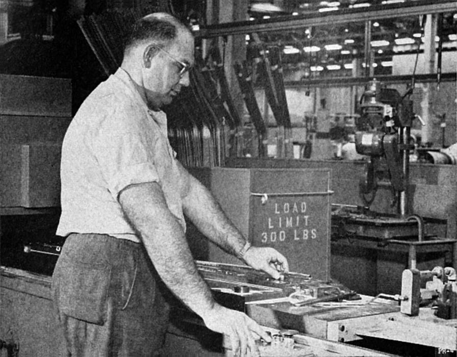
Round nickel tubes, .045 inches in diameter, form the envelope for the combustion chamber, nozzle and exit area of the thrust chamber. The tubes are changed to rectangular form in a tube press, which not only changes the tubes from straight and round to rectangular, but to the exact cross-sectional contour of the chamber.
Click image for a 1260x984 pixel version of this image in a new window.
ROUND NICKEL TUBES, .045 in diameter, are pressed into rectangular form.
Scan by archive.org; cleanup by heroicrelics.
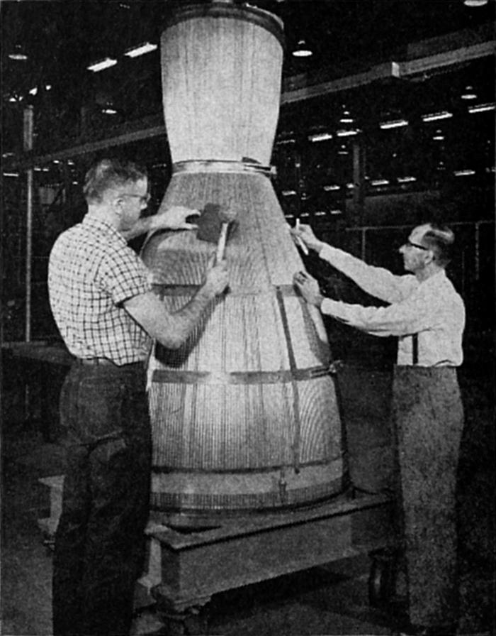
After the pressure forming, the tubes (approximately 300 [heroicrelics: the actual number is 292]) are placed against a torch-weld jig and held in place with steel bands for the welding operation. The tubes are joined in the jig by brazing with silver solder.
Click image for a 770x986 pixel version of this image in a new window.
FORMED TUBES are stacked on mandrel.
Scan by archive.org; cleanup by heroicrelics.
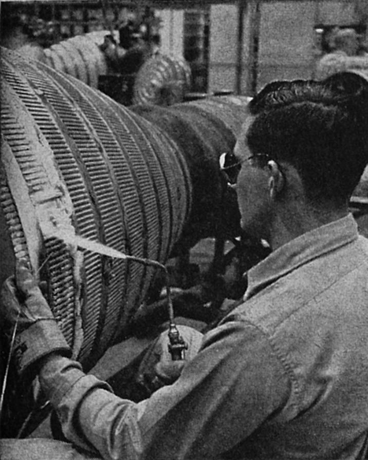
Approximately $300 worth of solder is used in this operation. The steel bands holding the tubes in position are welded to the tubes at intervals as reinforcing bands to absorb the stress resulting from the combustion pressure and heat expansion. In the region of the combustion chamber, the reinforcing bands form a solid continuous band.
Click image for a 791x990 pixel version of this image in a new window.
MOST CRUCIAL operation is tube soldering.
Scan by archive.org; cleanup by heroicrelics.
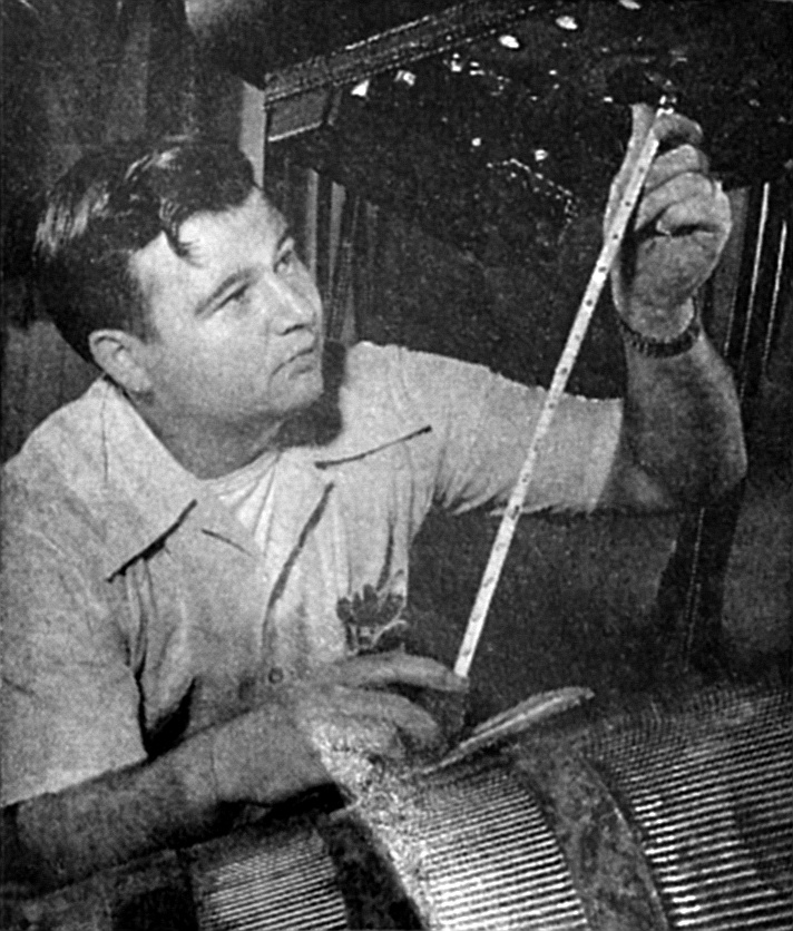
PENETRATION of solder checked by X-ray.
Scan by archive.org; cleanup by heroicrelics.
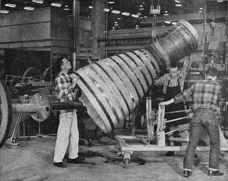
Following the brazing/welding operation, manifolds are attached to the ends and the injector plate mounted into position. After X-ray examinations, pressure checks and cold flow tests, the thrust chamber is ready for the installation of the main propulsion package of turbo pump, gas generator, main lines.
Click image for a 1249x992 pixel version of this image in a new window.
THRUST CHAMBER is mounted on large lathe for manifold preparation.
Scan by archive.org; cleanup by heroicrelics.
Click image for a 1308x836 pixel version of this image in a new window.
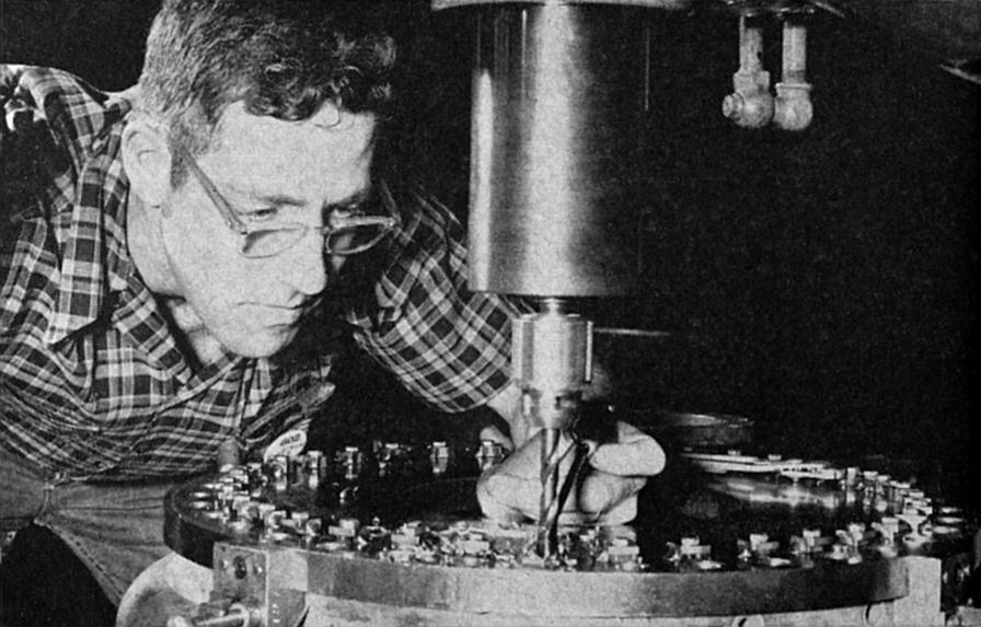
DRILLING OPERATION at manifold end of chamber for attachment of injector.
Scan by archive.org; cleanup by heroicrelics.
Click image for a 1316x841 pixel version of this image in a new window.
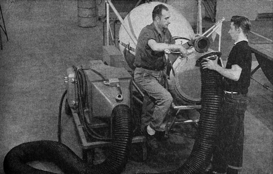
HOT AIR HEATER dries thrust chamber after cold-flow calibration
Scan by archive.org; cleanup by heroicrelics.
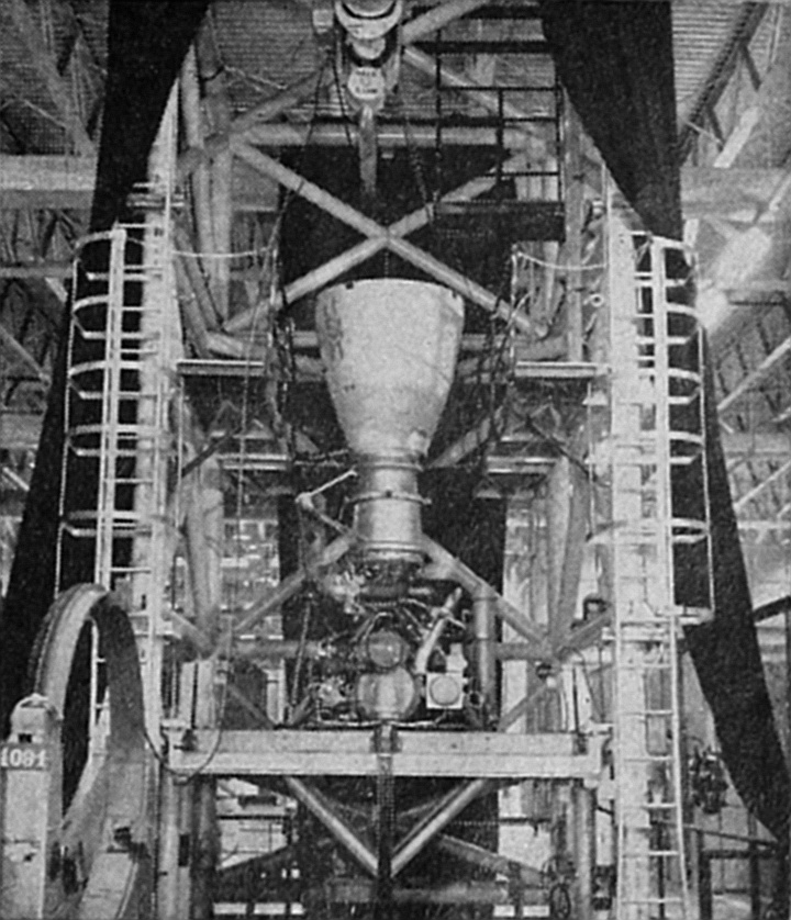
ENGINE in thrust alignment tower.
Scan by archive.org; cleanup by heroicrelics.
The contents of this page, in their entirety, were reproduced from the October 20, 1958 issue of Missiles and Rockets, available on archive.org. Since these magazines are freely available on archive.org, I assume that the copyright has been transferred to the public domain.

