
Museum of Flight's F-1 Engine Support
As noted in a vintage Marshall Space Flight Center internal memo, there is some concern that the nozzle extension on F-1 rocket engines displayed vertically are not designed to support the weight of the entire engine. Based on the number of F-1s displayed as such, it seems that this concern primarily addresses a theoretical problem, but Marshall Space Flight Center, for a time, chose to use throat supports to alleviate this issue for at least two engines which were installed at the Center.
In February 2017, F-1 engine F-6049 was transferred from MSFC to Seattle's Museum of Flight (which I have not yet visited). However, Marshall discouraged the museum from using a throat support, as it would have put the entire weight of the engine on the copper injector plate, possibly deforming it over time. Therefore, when the museum installed it vertically on March 14 and 15, 2017, it was not erected on a throat support, but rather a mount of the museum's own design.
The mount used by the museum fits between the main thrust chamber and the nozzle extension. The thrust chamber rests on the mount while the nozzle extension hangs from it, so that the weight of the engine is borne neither by the injector nor the nozzle extension, but rather by the mount itself.
Photos of the mount are not available, but the above-linked installation video does show the mount due to its proximity to the engine during installation. Looking very much like a circus elephant's stand, it has a reinforced pedestal base supporting circular ring.
It would seem that the nozzle extension was placed over the mount and a disc was placed on top of the mount's circular ring. The engine's thrust chamber was then placed on top of the disc, thus supporting the thrust chamber. The thrust chamber and nozzle extension were bolted together in much the ordinary fashion, but with the the disc sandwiched between the two, resulting in the nozzle extension hanging from the disc.
The first two screen captures show the mount's base and ring prior to the disc's installation:
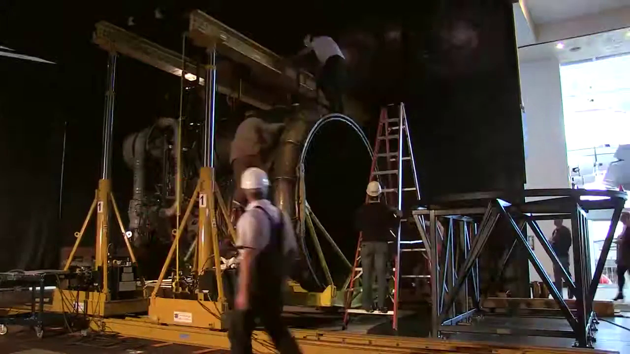
Click image for a 1280x720 pixel version of this image in a new window.
From the "Installing
Apollo's Saturn V Rocketdyne F-1 rocket engine timelapse - The Museum of
Flight, Seattle" YouTube video.
Screen capture by heroicrelics.
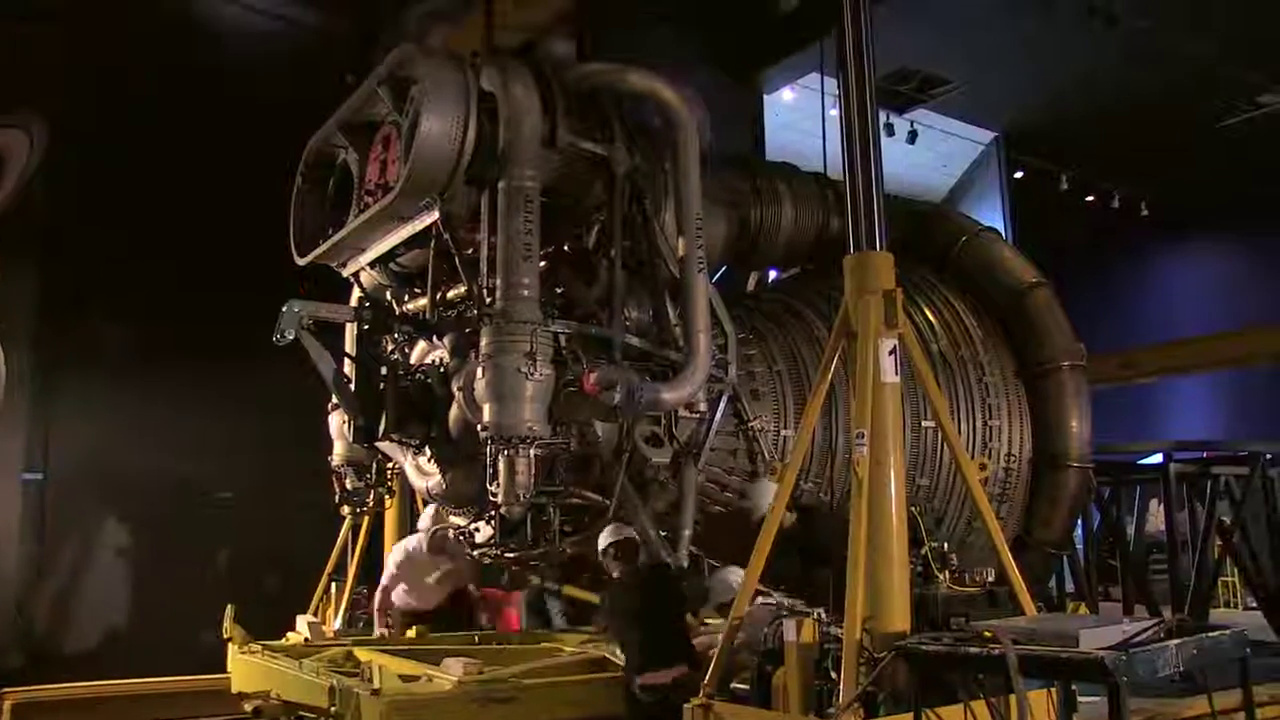
Click image for a 1280x720 pixel version of this image in a new window.
From the "Installing
Apollo's Saturn V Rocketdyne F-1 rocket engine timelapse - The Museum of
Flight, Seattle" YouTube video.
Screen capture by heroicrelics.
The shiny disc can be seen atop the nozzle extension as the thrust chamber is being positioned above it:
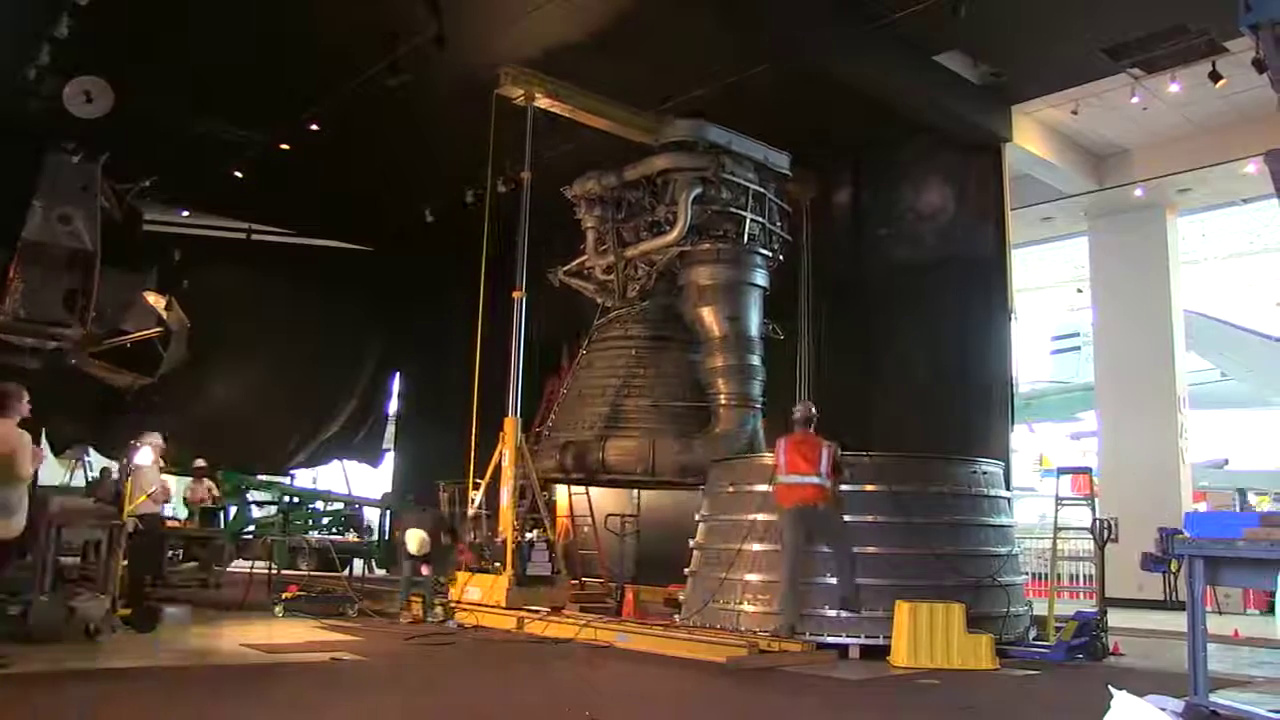
Click image for a 1280x720 pixel version of this image in a new window.
From the "Installing
Apollo's Saturn V Rocketdyne F-1 rocket engine timelapse - The Museum of
Flight, Seattle" YouTube video.
Screen capture by heroicrelics.
A docent at the museum provided some photos of the joint between the thrust chamber and the nozzle extension. The support disc is fairly unobtrusive, and one would likely not notice it unless specifically looking for it:
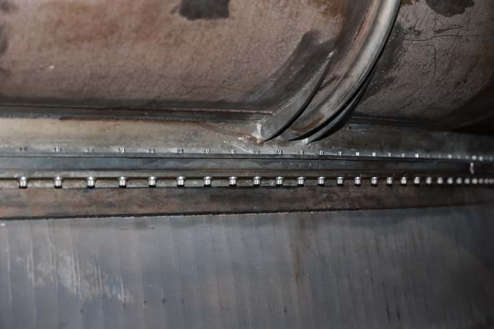
Photo courtesy of Dieter Zube.
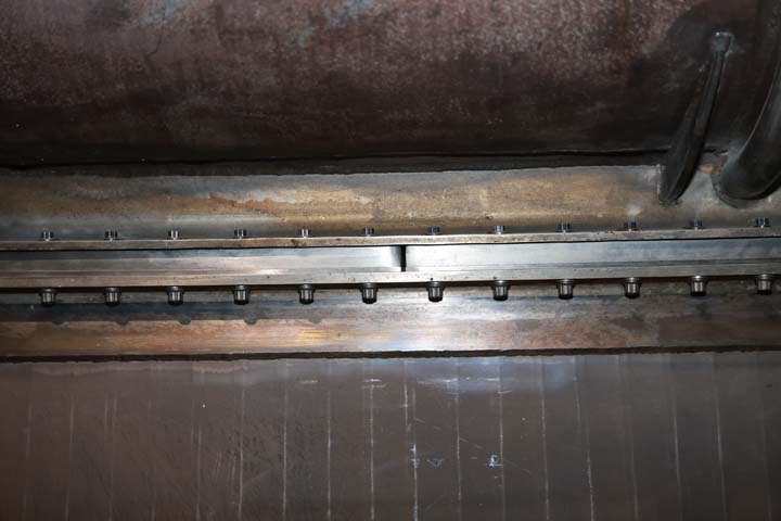
Photo courtesy of Dieter Zube.