
Lunar Roving Vehicle (LRV) Major Subsystems
This page hopes to document the major subsystems of the Apollo Lunar Roving Vehicle.
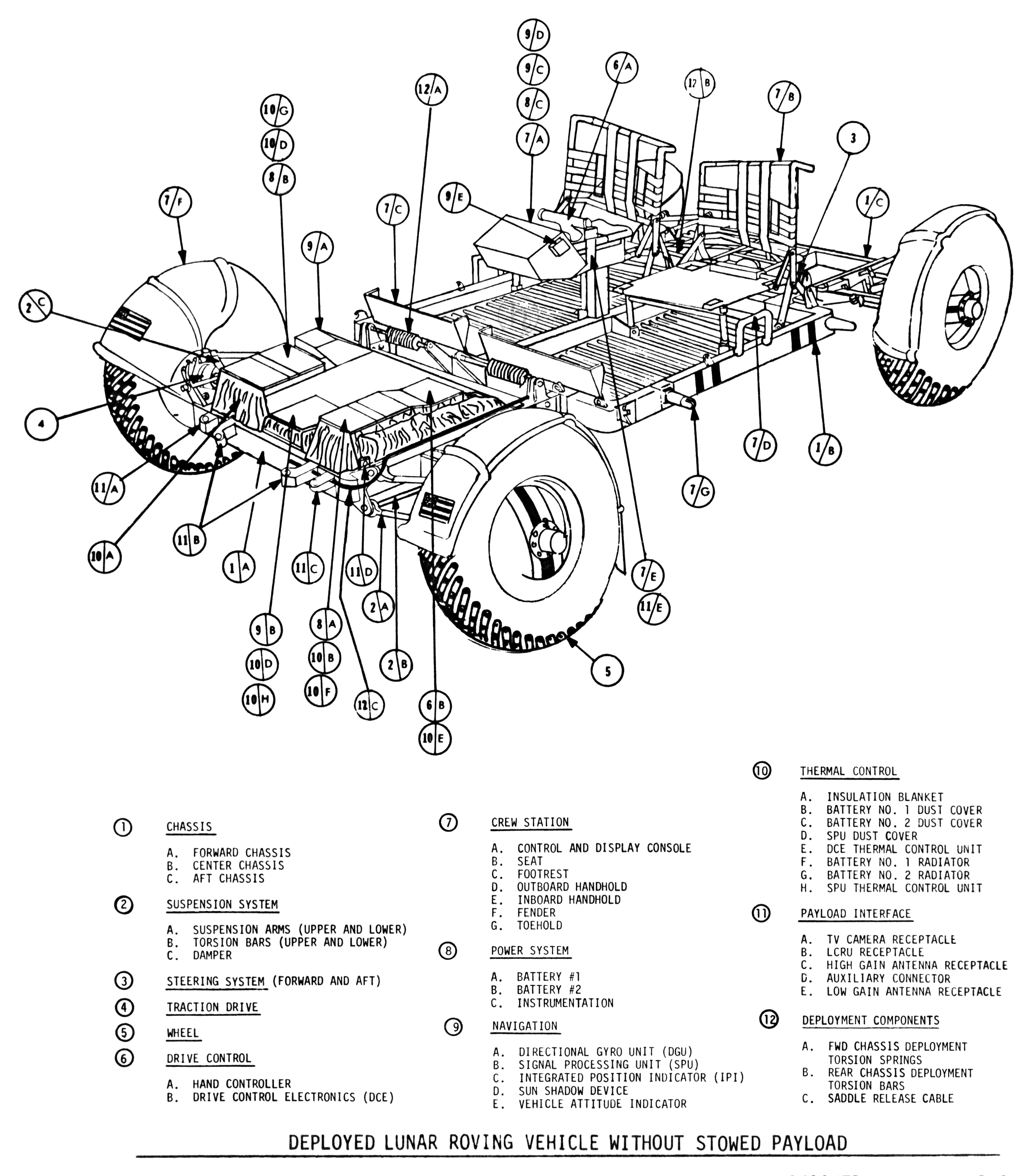
Upon deployment, the LRV is carries minimal equipment, due to being folded up in the Lunar Module's Quad 1. Only items which can be folded up (such as the seats) or which could remain intact while the LRV folded around it (such as the control and display console) came pre-installed on the rover.
Click image for a 4789x5460 pixel version of this image in a new window.
From page 1-2 of the Lunar Roving Vehicle Operations Handbook July 7,
1971, located in the LRV Collection, Dept. of Archives/Special
Collections, M. Louis Salmon Library, University of Alabama in
Huntsville. Also available electronically from the Apollo Lunar Surface
Journal.
Scan and restoration by heroicrelics.org.
Callouts on this diagram include
-
Chassis
- Forward chassis
- Center chassis
- Aft chassis
-
Suspension System
- Suspension arms (upper and lower)
- Torsion bars (upper and lower)
- Damper
- Steering System (Forward and Aft)
- Traction Drive
- Wheel
-
Drive control
- Hand controller
- Drive Control Electronics (DCE)
-
Crew Station
- Control and Display Console
- Seat
- Footrest
- Outboard Handhold
- Inboard Handhold
- Fender
- Toehold
-
Power System
- Battery #1
- Battery #2
- Instrumentation
-
Navigation
- Direction Gyro Unit (DGU)
- Signal Processing Unit (SPU)
- Integrated Position Indicator (IPI)
- Sun Shadow Device
- Vehicle Attitude Indicator
-
Thermal Control
- Insulation Blanket
- Battery No. 1 Dust Cover
- Battery No. 2 Dust Cover
- SPU Dust Cover
- DCE Thermal Control Unit
- Battery No. 1 Radiator
- Battery No. 2 Radiator
- SPU Thermal Control Unit
-
Payload Interface
- TV Camera Receptacle
- LCRU Receptacle
- High Gain Antenna Receptacle
- Auxiliary Connector
- Low Gain Antenna Receptacle
-
Deployment Components
- Fwd Chassis Deployment Torsion Springs
- Rear Chassis Deployment Torsion Bars
- Saddle Release Cable
The various equipment was stowed in the descent stage's modularized equipment stowage assembly (MESA), located in Quad 4 (note that later missions had an enlarged MESA to store the additional equipment), and in Quad 3. The astronauts had to unpack the equipment from the MESA and Quad 3, install it on the LRV, and make the necessary electrical connections.
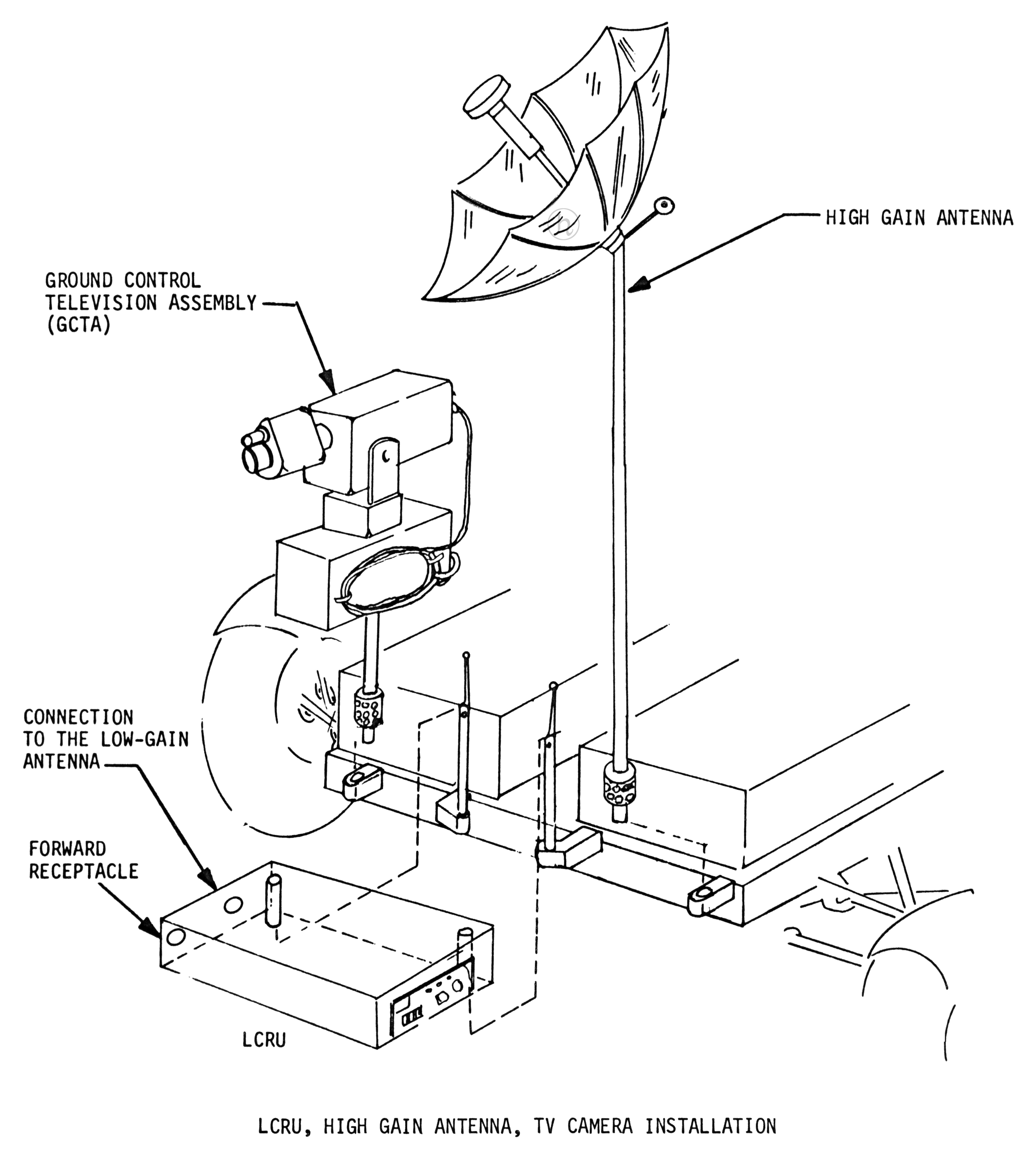
Among the equipment mounted on the LRV was the lunar communications relay unit (an electronics box which allowed two-way communication of voice, television, and telemetry between ground controllers and the astronauts while on EVA), a high gain antenna, and the ground control television assembly (TV camera):
Click image for a 4706x5248 pixel version of this image in a new window.
From page 4-2 of the Lunar Roving Vehicle Operations Handbook July 7,
1971, located in the LRV Collection, Dept. of Archives/Special
Collections, M. Louis Salmon Library, University of Alabama in
Huntsville. Also available electronically from the Apollo Lunar Surface
Journal.
Scan and restoration by heroicrelics.org.
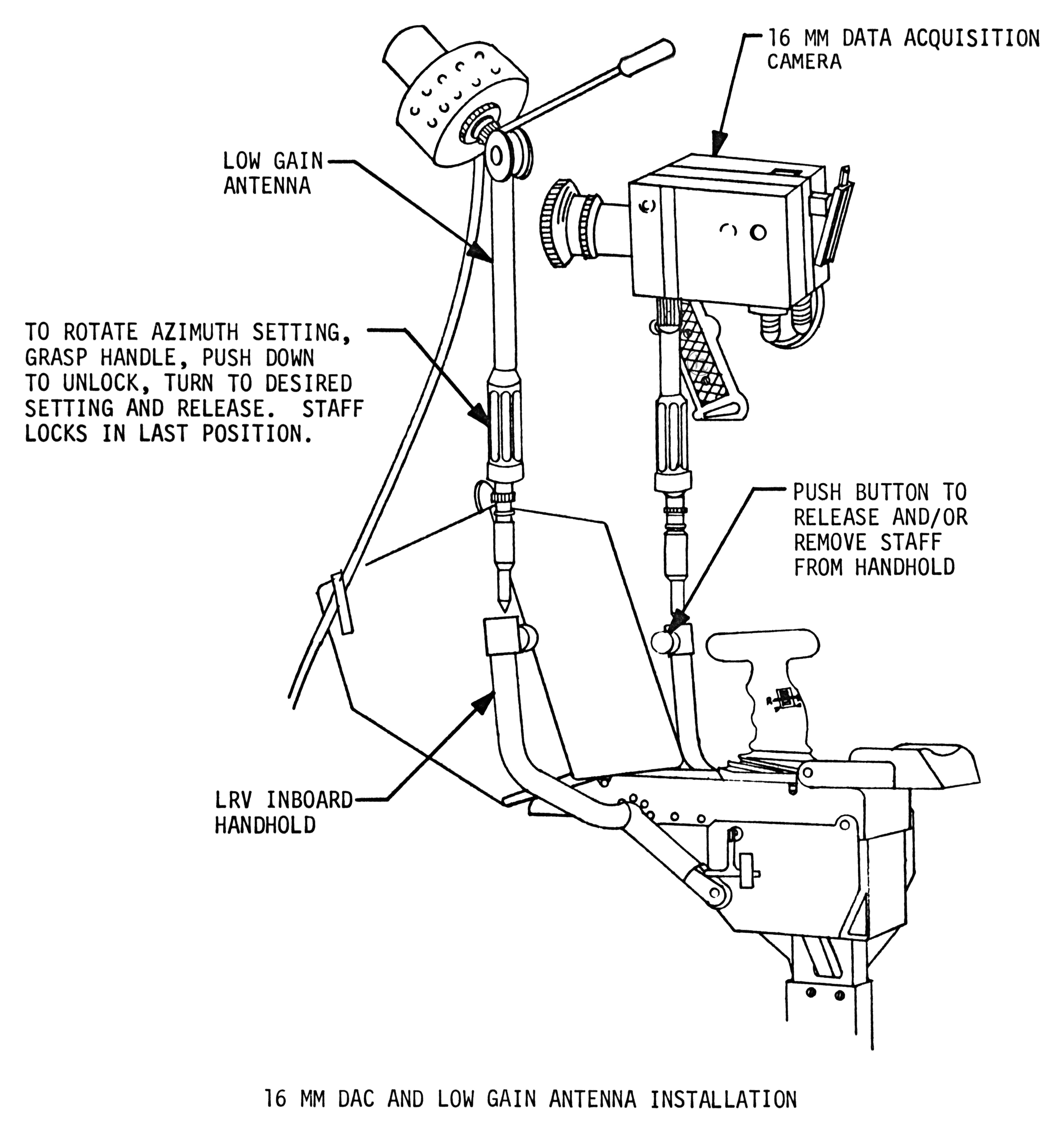
The high gain antenna had to be pointed at Earth, and so was of limited use while the LRV was in motion. There was additionally a low gain antenna, as well as a 16 mm "data acquisition camera", which was the official NASA term for a movie camera:
Click image for a 4285x4561 pixel version of this image in a new window.
From page 4-5 of the Lunar Roving Vehicle Operations Handbook July 7,
1971, located in the LRV Collection, Dept. of Archives/Special
Collections, M. Louis Salmon Library, University of Alabama in
Huntsville. Also available electronically from the Apollo Lunar Surface
Journal.
Scan and restoration by heroicrelics.org.
In addition to the equipment which was considered part of the LRV, the rover also carried various tools and supplies required by the astronauts as they performed their lunar surface geology. The tool load varied from one mission to another.
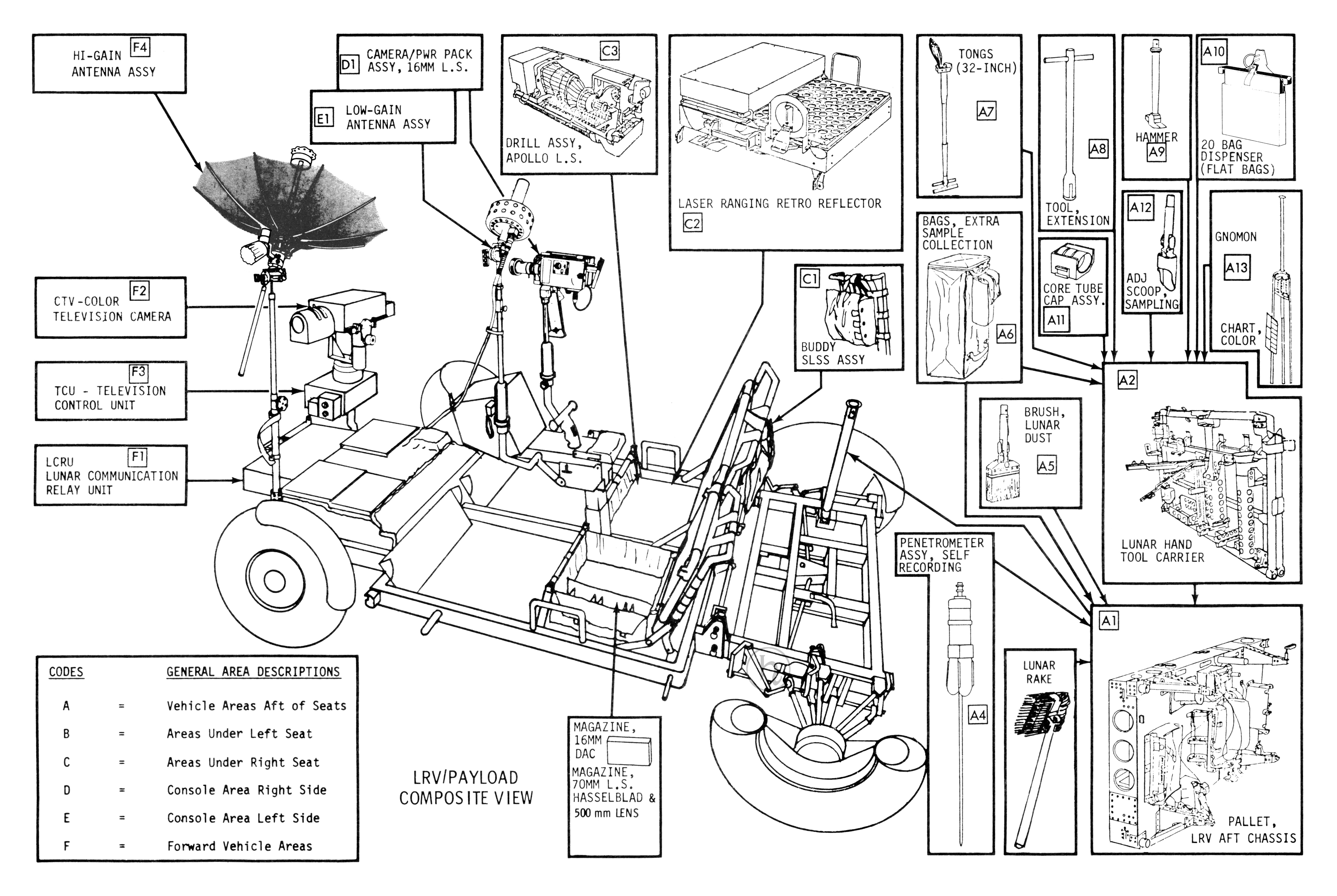
In order to help the astronauts remember where equipment was stored (and thus allow them to quickly find it and thus make the most of their time on the lunar surface), the LRV was divided up into zones, or "general areas," and equipment was placed in its designated location. These locations included under the astronauts' seats, the LRV aft pallet assembly, and the lunar hand tool carrier (which mounted on the aft pallet). Major components of the LRV were mounted in the forward vehicle and console areas.
Apollo 15 LRV Payload
Click image for a 5982x4010 pixel version of this image in a new window.
From page 81 of the Apollo 15 Press Kit, located in Apollo 14
collection and Misc Material level 1 box 1, Dept. of Archives/Special
Collections, M. Louis Salmon Library, University of Alabama in
Huntsville. Also available electronically from the heroicrelics
mirror.
Scan and restoration by heroicrelics.org.
Equipment area descriptions include
| CODES | GENERAL AREA DESCRIPTIONS |
|---|---|
| A = | Vehicle Areas Aft of Seats |
| B = | Areas Under Left Seat |
| C = | Areas Under Right Seat |
| D = | Console Area Right Side |
| E = | Console Area Left Side |
| F = | Forward Vehicle Areas |
Callouts on this diagram include
- F4 Hi-Gain Antenna
- F2 CTV - Color Television Camera
- F3 TCU - Television Control Unit
- F1 LCRU - Lunar Communication Relay Unit
- D1 Camera/Pwr Pack Assy, 16mm L.S.
- E1 Low-Gain Antenna Assy
- C3 Drill Assy, Apollo L.S.
- Magazine, 16mm DAC; Magazine, 70mm L.S. Hasselblad & 500mm Lens
- C2 Laser Ranging Retro Reflector
- C1 Buddy SLSS Assy
- A7 Tongs (32-inch)
- A6 Bags, Extra Sample Collection
- A8 Tool, Extension
- A11 Core Tube Cap Assy.
- A9 Hammer
- A12 Adj Scoop, Sampling
- A10 20 Bag Dispenser (Flat Bags)
- A13 Gnomon; Chart, Color
- A2 Lunar Hand Tool Carrier
- A5 Brush, Lunar Dust
- A4 Penetrometer Assy, Self Recording
- Lunar Rake
- A1 Pallet, LRV Aft Chassis