
J-2 With Callouts
This page serves as a repository for photos and diagrams of the J-2 rocket engine with callouts identifying major (and even not-so-major) components.

Click image for a 5779x4086 pixel version of this image in a new window.
Adapted from p. 1 of a Rocketdyne "J-2 Engine Facts" handout. Located in the Mauldin Collection, Dept. of Archives/Special
Collections, M. Louis Salmon Library, University of Alabama in
Huntsville.
Scan, clean-up, and adaptation by heroicrelics.
The engine components identified on the left-hand graphic include
- Fuel Inlet Duct
- Gimbal
- Start Tank
- Fuel Turbopump
- Oxidizer Turbine By-Pass Valve
- Oxidizer Inlet Duct
- Oxidizer Turbopump
- Turbine Exhaust Duct
- Heat Exchanger
- Exhaust Manifold
- Fuel Manifold
The engine components identified on the right-hand graphic include
- High Pressure Oxidizer Duct
- Propellant Utilization Valve
- Primary Flight Instrumentation
- Main Oxidizer Valve
- LOX B/V [Bleed Valve; used to help condition the engine prior to start by bleeding trapped gas from the oxidizer systems]
- Fuel B/V [Bleed Valve; similar to the LOX B/V]
- Gas Generator
- Elec. Control Package
- Oxidizer Turbine By-Pass Valve
- Main Fuel Valve
- Thrust Chamber
Another, similar diagram, but with additional items called out:

Click image for a 5235x3375 pixel version of this image in a new window.
From p. 46 of the Arnold Engineering Development Center report Altitude
Testing of the J-2 Rocket Engine in Propulsion Engine Test Cell (J-4) (Tests
J4-1554-01 Through J4-1554-11), July 1967. Located in the Thomson
collection, Dept. of
Archives/Special Collections, M. Louis Salmon Library, University of
Alabama in Huntsville.
Scan and clean-up by heroicrelics.
The engine callouts on the left-hand graphic include
- Fuel Inlet Duct
- Fuel Turbopump
- Start Tank Discharge Valve
- Main Fuel Valve
- Turbine Bypass Duct
- Oxidizer Turbine Bypass Duct
- Oxidizer Inlet Duct
- Oxidizer Turbopump
- Auxiliary Flight Instrumentation Package
- Exhaust Manifold
The callouts on the right-hand graphic include
- Gimbal
- Start Tank
- Oxidizer Inlet Duct
- Pneumatic Control Package
- Propellant Utilization Valve
- Heat Exchanger
- Thrust Chamber
- Fuel Inlet Duct
- Fuel Bleed Valve
- Gas Generator
- High Pressure Fuel Duct
- Electrical Control Package
- Primary Flight Instrumentation Package
- Main Fuel Valve
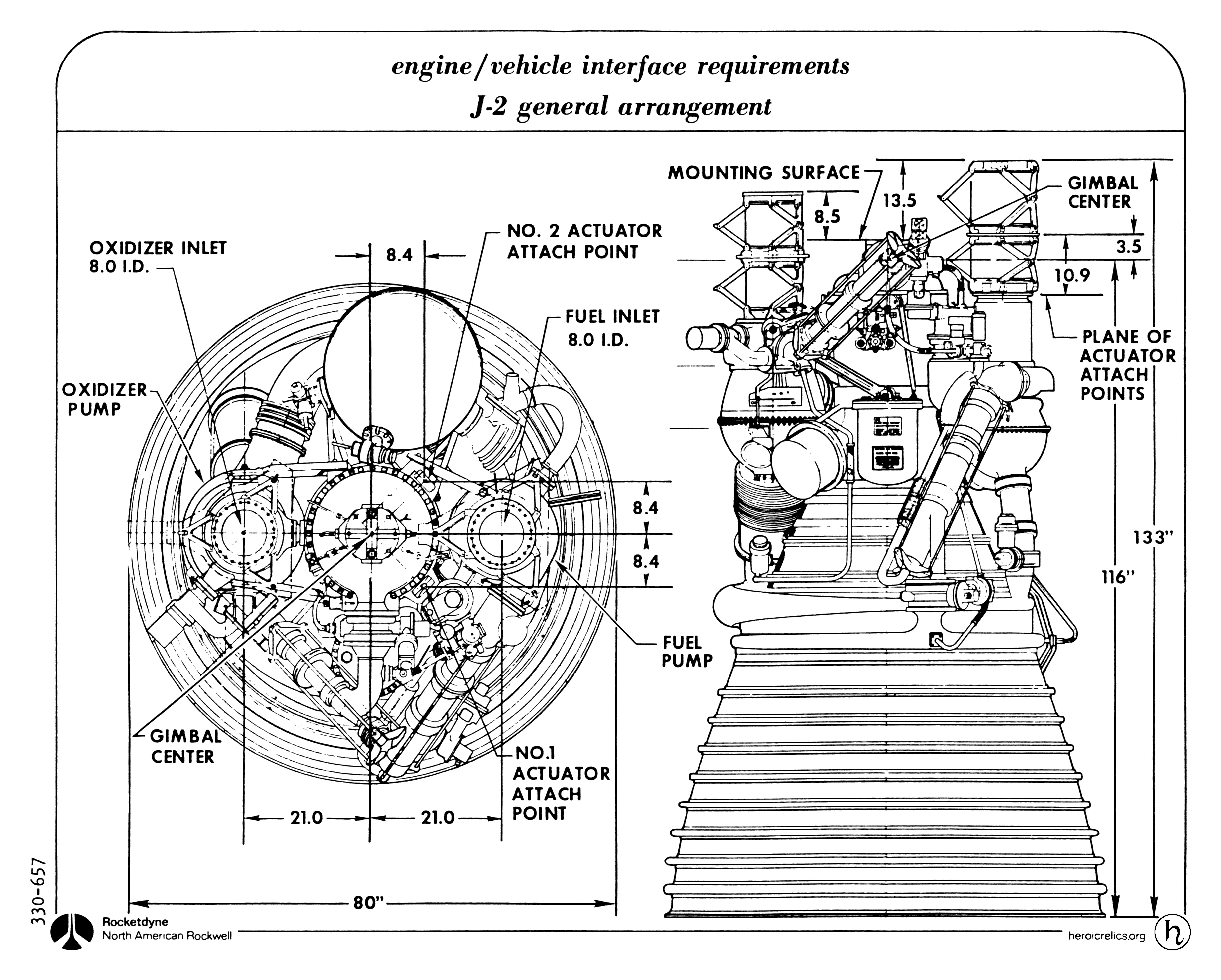
This diagram includes not only call-outs but also dimensional information:
Click image for a 6136x4924 pixel version of this image in a new window.
From p. 1 of a Rocketdyne "J-2/J-2S Engines"
handout. Located in the Morea Saturn and J-2 binder, Dept. of Archives/Special
Collections, M. Louis Salmon Library, University of Alabama in
Huntsville.
Scan and clean-up by heroicrelics.
The engine callouts on the left-hand graphic include
- Oxidizer Inlet, 8.0 I.D.
- Oxidizer Pump
- Gimbal Center
- 21.0 from Center of Oxidizer Inlet to Gimbal Center
- 80" Overall Diameter
- No. 2 Actuator Attach Point
- 8.4 from Gimbal Center to No. 2 Actuator Point
- Fuel Inlet, 8.0 I.D.
- 8.4 from No. 2 Actuator Point to Center of Fuel Inlet
- Fuel Turbopump
- 8.4 from Center of Fuel Inlet to No. 1 Actuator Point
- No. 1 Actuator Point
- 21.0 from Gimbal Center to Center of Fuel Inlet
The callouts on the right-hand graphic include
- Mounting Surface [presumably Gimbal forward face]
- 8.5 from Oxidizer Inlet forward face to Gimbal forward face
- 13.5 from Fuel Inlet forward face to Gimbal forward face
- Gimbal Center
- Plane of Actuator Attach Points
- 116" from Gimbal Center to Thrust Chamber Exit Plane
- 133" from Fuel Inlet forward face to Thrust Chamber Exit Plane