
J-2 Rocket Engine Thrust Chamber
With a thrust of up to 230,000 lb., the J-2 rocket engine was the most powerful liquid hydrogen engine that flew in the 1960s, holding that title until the Space Shuttle Main Engine (SSME) flew in April of 1981. Like Rocketdyne's other man-rated engines of that era (and unlike several of Rocketdyne's missile engines), all of the engine's accessories, such as its turbopumps, heat exchanger, and hydraulic pumps, were mounted directly on the rocket engine's thrust chamber.
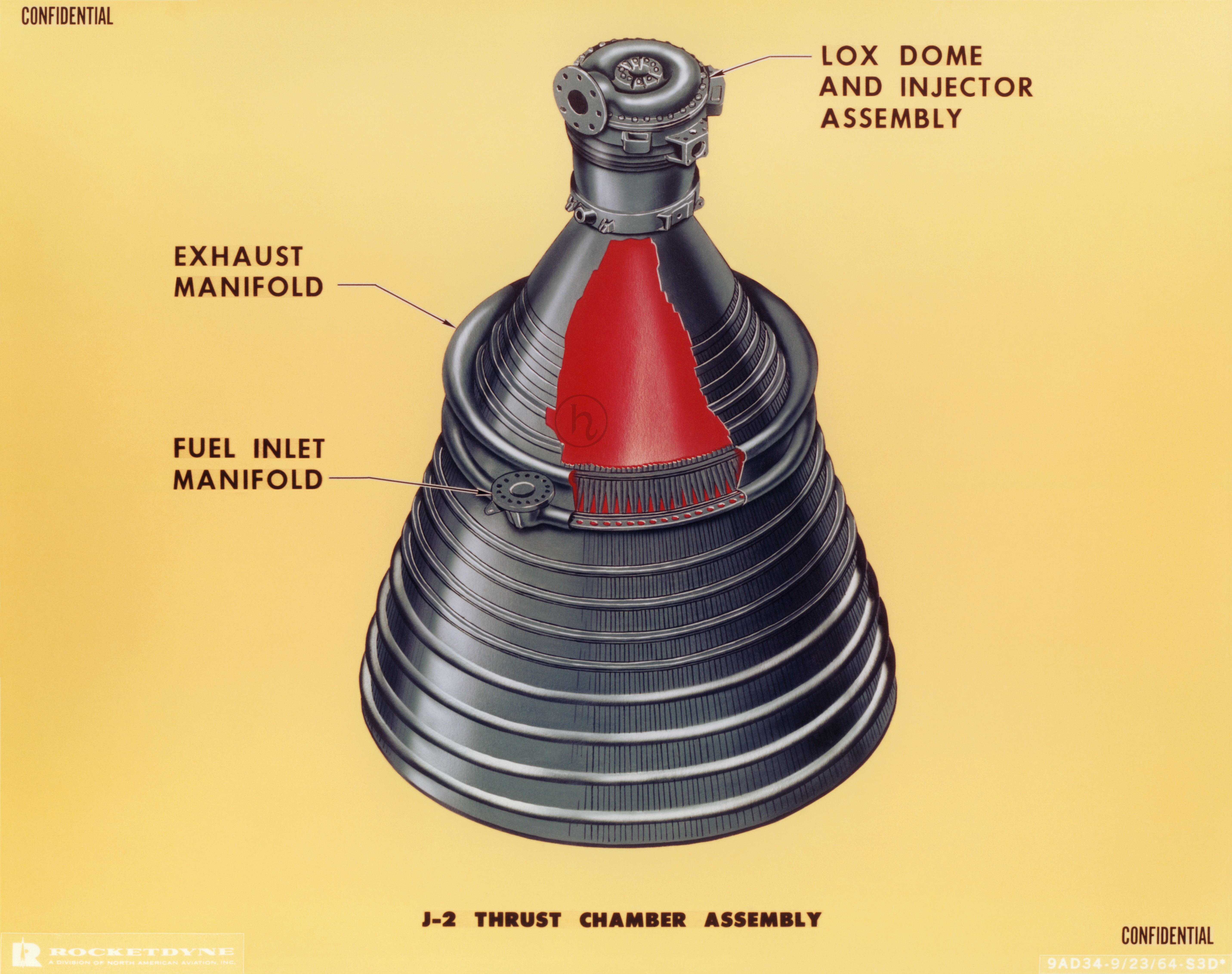
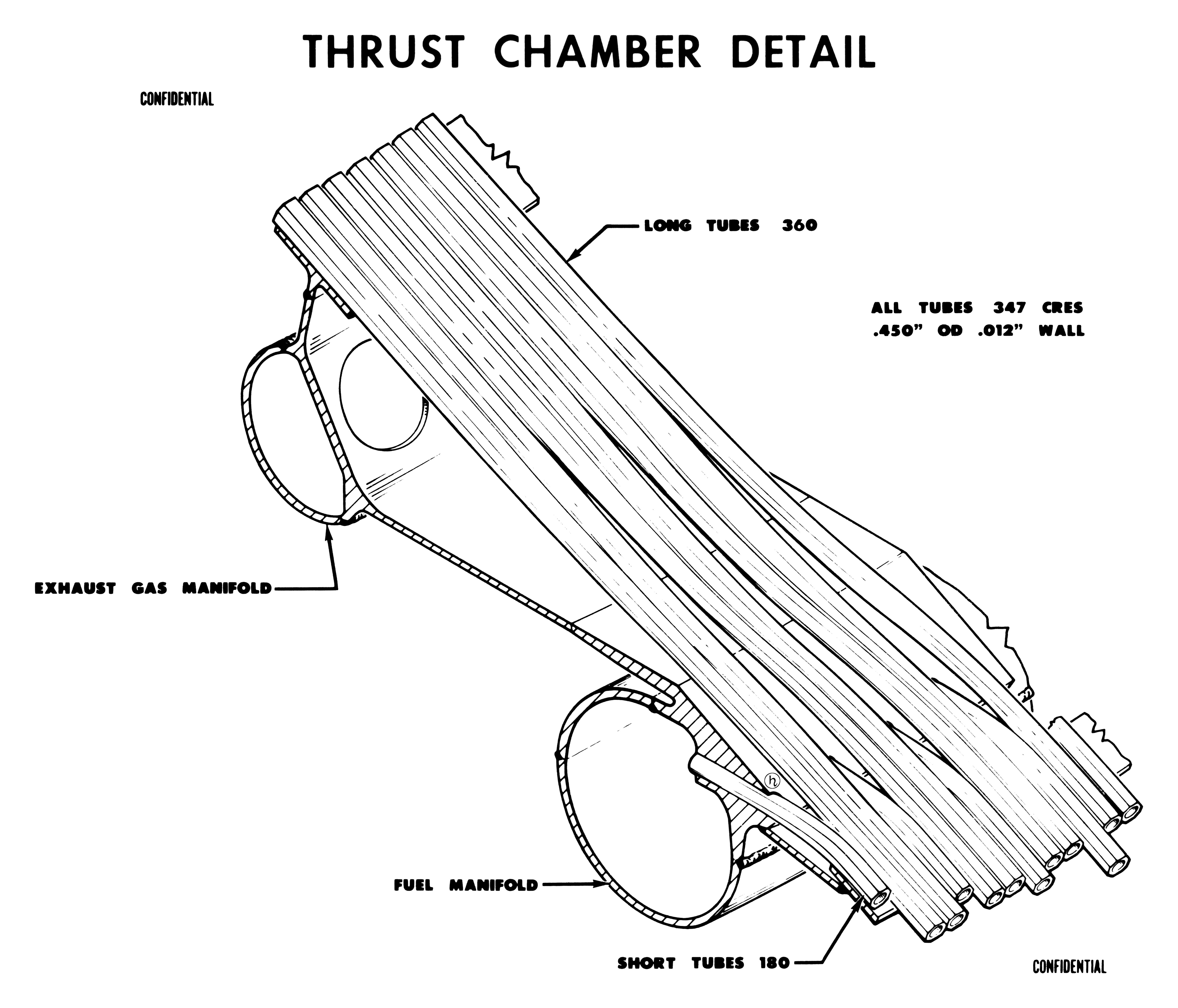
The J-2 rocket engine had a tubular-walled, bell-shaped thrust chamber, consisting of a cylindrical combustion chamber, a narrowing throat section, and an expansion section. The thrust chamber body was constructed of stainless steel regenerative cooling tubes consisting of 180 half-length "down" tubes and 360 full-length "up" tubes. They were brazed together and supported by bands around the tubes for external stiffening. This construction allowed the fuel to flow through the tubing to cool the thrust chamber walls and to be converted to a gaseous state before reaching the injector and subsequently combusted while at the same time enabling the high expansion ratio of 27.15 to 1.
Click image for a 5726x4527 pixel version of this image in a new window.
From p. 34 of J-2 Engine Training Aids, R-5860, in the Dieter
Huzel Collection of the archives of
the U.S. Space & Rocket Center.
Scan and clean-up by heroicrelics.
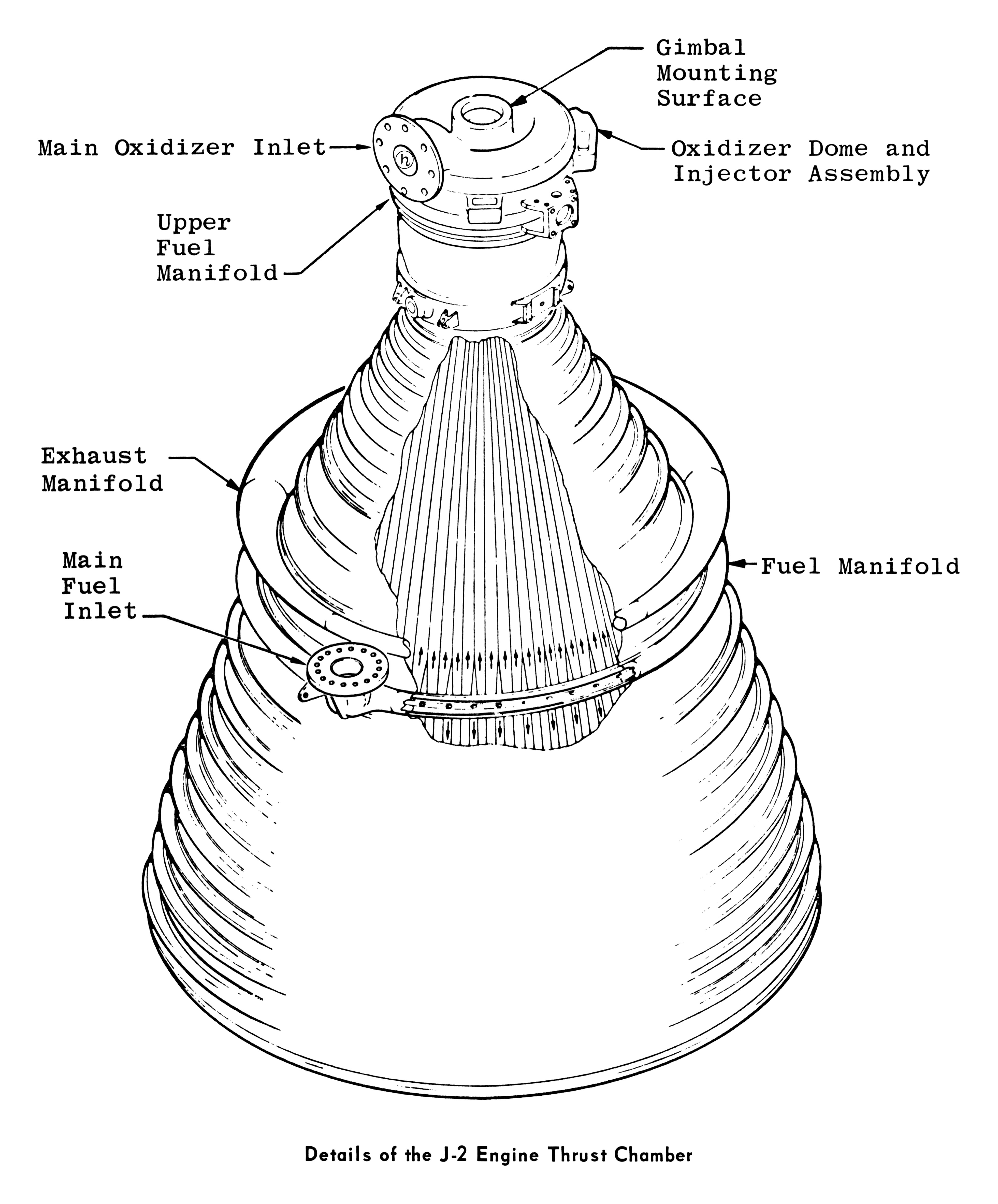
The thrust chamber was 8' 6" (80") in diameter at the exit plane. While the entire engine was 11' 1" (133") tall, that figure included the fuel inlet duct and turbopump. Less definitive information is available about the height of bare thrust chamber, although I do have one diagram which seems to indicate that the thrust chamber, from exit plane to the forward surface of the injector, is 8' 9.1" (105.1").
Click image for a 3923x4733 pixel version of this image in a new window.
From p. 47 of Altitude Testing of the J-2 Rocket Engine in Propulsion
Engine Test Cell (J-4) (Tests J4-1554-01 through J4-1554-11). Located
in the Thomson Collection, Dept. of
Archives/Special Collections, M. Louis Salmon Library, University of
Alabama in Huntsville. Available in electronic format from the Defense Technical
Information Center.
Scan and clean-up by heroicrelics.
The 360 full-length tubes ran from the reverse-flow manifold (called a "fuel return manifold" on some other engines) at the engine's exit plane to the injector. These tubes delivered the hydrogen fuel to the engine's injector.
The 180 half-length tubes were introduced at the engine's fuel manifold and carried the hydrogen from the fuel manifold to the reverse-flow manifold. With 360 "up" tubes and 180 "down" tubes, each "down" tube was inserted between pairs of two "up" tubes at the fuel manifold. This can be seen here, where brackets on the aft side of the fuel manifold are brazed onto pairs of "up" tubes and the "down" tubes appear between these brackets:

Click image for more information about this picture; opens in a new window.
Photo by heroicrelics.org.
The engine's exhaust manifold was located just forward of the engine's fuel manifold. The gaps introduced between pairs of "up" tubes (sometimes called "cat eyes" for their diamond shape) to make room for the "down" tubes also allowed turbine exhaust gases from the exhaust manifold to flow into the thrust chamber:
Click image for a 5083x4353 pixel version of this image in a new window.
From p. 34 of J-2 Engine Training Aids, R-5860, in the Dieter
Huzel Collection of the archives of
the U.S. Space & Rocket Center.
Scan and clean-up by heroicrelics.
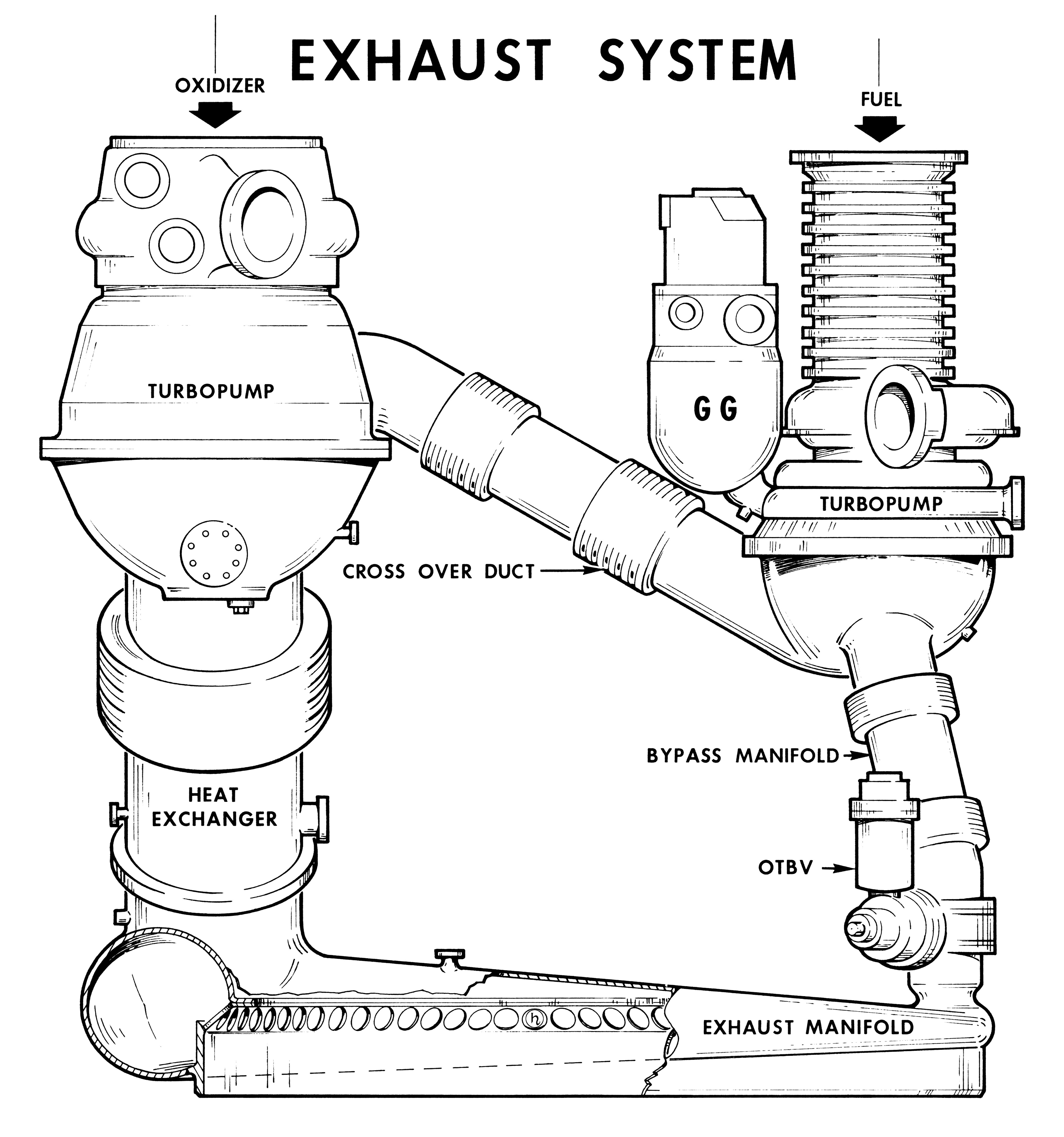
On the J-2, hot gas from the gas generator passed first through the fuel turbopump's turbine. Some of this gas was routed directly to the exhaust manifold, but the bulk of it travelled through the cross over duct to the oxidizer turbopump's turbine. After passing through the engine's heat exchanger, this gas, too, entered the exhaust manifold.
Click image for a 4074x4352 pixel version of this image in a new window.
From p. 94 of a Rocketdyne "J-2 Engine Facts" handout. Located in the Mauldin Collection, Dept. of Archives/Special
Collections, M. Louis Salmon Library, University of Alabama in
Huntsville.
Scan and clean-up by heroicrelics.
As depicted in the diagram above and the photo below, the exhaust manifold wall adjacent to the exterior of thrust chamber had a series of circular cut-outs. The exhaust gases flowed into the exhaust manifold from the LH2 and LOX turbopumps turbines, passed through these circular cut-outs, and entered the engine's main exhaust stream via the gaps between the pairs of "up" tubes. The forward end of the "cat eyes" can be seen in the photo below.

Click image for more information about this picture; opens in a new window.
Photo by heroicrelics.org.