F-1 Rocket Engine G4049 Engine Vertical Installer Data Sheet
This page reproduces a G4049 engine vertical installer data sheet. For additional information, photos, and diagrams, see my F-1 rocket engine G4049 engine vertical installer page.
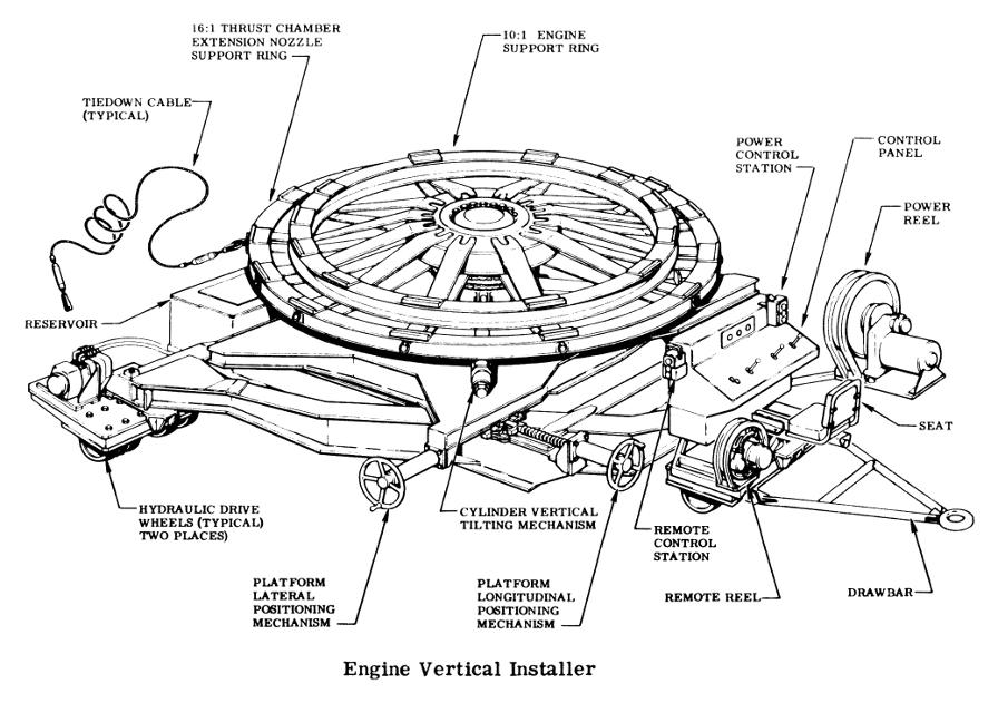
The engine vertical installer is an electrohydraulic-operated, self-propelled, lifting and positioning unit for the engine. (See the figure for leading particulars.) The vertical installer consists of a dual-pressure hydraulic system, electrical system, control console, manually-operated tilting mechanism, manually-operated horizontal positioning mechanism, a hydraulically-operated azimuth drive, a pair of hydraulically-operated drive wheels and gearboxes, and a three-stage lifting cylinder, all supported on a triangular frame. Twelve wheels, including the hydraulic drive wheels, support the vehicle frame. It also has an attachable tow bar. The vertical installer platform or cylinder can be operated manually with control valves on the control panel, or remotely using the remote-control station. The drive wheels can be operated from the control panel only.
Click image for a 2075x1461 pixel version of this image in a new window.
Photo courtesy Vince Wheelock.
Cleanup by heroicrelics.
Length 230 inches Width 206 inches Height 70 inches Gross Weight 27,000 pounds Maximum Load Capacity 17,500 pounds
20,000 pounds (units incorporating MD2 change)Proof-Load (at 24-month intervals or whenever lift cylinder is replaced) 45,000-pound vertical test-load
8,200-pound side test-load (cylinder retracted)
3,300-pound side test-load (cylinder extended)
Towing Speed 1/2 mph, loaded
1 mph, unloadedDriving Speed 1/2 mph Platform Rotation 360 degrees Platform Rotation Speed 1/3 rpm, maximum
1/175 rpm, minimumPlatform Traverse (manual operation) 8 inches each side of centerline Platform Tilt (manual operation) 2 degrees each side of centerline Lifting Speed 40 inches a minute, maximum
3 inches a minute, minimumFluid Hydraulic fluid (MIL-H-5606) Reservoir 140 gallons Relief Valves 2,000 psig
270 psigPressure Gages High-pressure: 0 to 3000 psi
Low-pressure: 0 to 600 psiFixed Orifices 0.020 inch - Wheel drive pilot line (at lift cylinder)
0.086 inch - Wheel drive valves
0.094 inch - Azimuth remote valve
0.125 inch - Lift cylinder remote valveSolenoid Valves 4-way
2-wayHydraulic Motors Hydraulic pressure Electric Motor 440 vac, 1,800 rpm, 20 hp Hydraulic Pumps 10 gpm at 3,000 psig
30 gpm at 500 psigHigh-Pressure System 0 to 2,000 psig Low- Pressure System 0 to 270 psig Controls
- Cylinder control
- LH and RH drive control
- Azimuth control
Filters 20-micron hydraulic Lifting Cylinder 3 Stage
- 1st 20-inch stroke
- 2nd 28.5-inch stroke
- 3rd 31.5-inch stroke
Temperature Gage +30° to +220° F range with a +200° F Redline

