
Inboard Profile - Apollo, Complete
While browsing a document on the NASA Technical Report Server, I ran across a nice diagram of the full CSM/SLA. Part of a foldout, it was unfortunately spread out over five separate pages in the original PDF file. Additionally, rather than overlapping the foldout pages, when the diagram was scanned there were actually gaps between the pages of the foldout, resulting in an incomplete diagram.
Luckily, I found another document with a similarly-butchered foldout, but the "missing" areas were slightly different than the first document. The second document was unfortunately scanned at a lower resolution than the first document and was also a poorer-quality scan. Thus, I primarily referred to the second document and manually reconstructed the full diagram.
I wound up spending way too much time on this diagram, but I think it turned out rather nicely. It details most of the external features of the Apollo spacecraft, including the launch escape tower with its Q-ball, canards, pitch control motor, tower jettison motor, and wire harnesses leading to the command module; the Command Module, with its side and rendezvous windows, steam vent, urine dump port, and the pitch, yaw, and roll thrusters and their respective access hatches; the Service Module, with its reaction control system (RCS) quads, Command-Service Module fairings, environmental control system radiators, and service propulsion system (SPS) engine nozzle extension; and the Lunar Module, nestled in the Spacecraft-Lunar Module Adapter (SLA) (from a North American Aviation document, this diagram has few details on the LM).
Strictly speaking, this diagram is correct for CSM-104 (Apollo 10). However, the CSM changed very little until the addition of the Scientific Instrument Module bay in Apollo 15 (CSM-112); the SIM bay was actually located inside a Service Module panel and was not visible until the panel was jettisoned. Similarly, the changes made to the Apollo 14 Service Module (the cryogenic oxygen tank and auxiliary battery added in the wake of the Apollo 13 explosion) were also internal. So, the CSM portion diagram should be fairly representative of Apollo 9 through Apollo 17 (the Lunar Module had plume deflectors added after Apollo 10 and the Lunar Roving Vehicle added to Apollo 15 and subsequent, but this diagram doesn't focus on the LM).
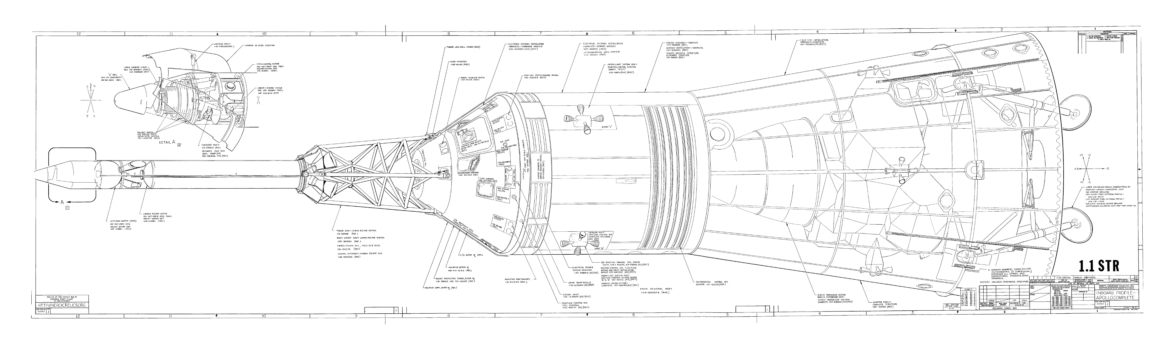
Click image for a 3935x1155 pixel version of this image in a new window.
Reconstructed from pp. 467-471 in the PDF (no page number in source document)
of the Command/Service
Module Systems Handbook (CSM 104), with additional information from
pp. 367-375 (no page number in source document) of Skylab Command
Service Module Systems Handbook (CSM 116-119).
Extraction, cleanup, and reconstruction by heroicrelics.
Additionally, I've prepared a PDF containing a 11244x3300 version of the reconstructed diagram. Download now [4 megabytes].