Apollo 4 Main Display
The AS-501 mission was the first launch of a Saturn V rocket. Due to George Mueller's October 31, 1963 "All-Up" decision, this first launch included an entire, active space vehicle, including Apollo 4, an unmanned, but still production-level, Apollo spacecraft.
The Apollo spacecraft was designed to be flown with a crew, so accommodations had to be made in order to fly it unmanned: A "Mission Control Programmer" (MCP) was installed in the space normally occupied by the crew couches. As noted in the Saturn V Launch Vehicle Flight Evaluation Report: AS-501, "As a result of being unmanned, a mission control programmer was installed while the crew couches, certain waste management items, certain displays and controls, and the postlanding ventilation valve were omitted."
Below is the Apollo 4 main display (commonly known as a "control panel"). As can be seen, in some cases individual components were deleted from the control panel while other times entire panels were replaced with blank plates:
Click image for a 10486x2930 pixel version of this image in a new window.
From page 11-33 (pages 384-389 in the PDF) of the Command Service
Module System Handbook, AS-501 (alternate
link).
Extraction and reconstruction by heroicrelics.
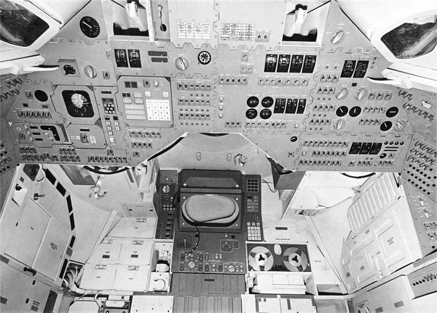
For comparison, here's a photo of a typical Block I command module main display console:
Click image for a 4261x3325 pixel version of this image in a new window.
From page 38 of an undated Apollo Spacecraft News Reference (this
particular copy appears to have been published sometime after February 26, 1966
[the launch of AS-201] but before July 5, 1966 [the launch of AS-203; recall
that AS-203 was launched before AS-202]). Located in the Saturn V Collection,
Dept. of Archives/Special
Collections, M. Louis Salmon Library, University of Alabama in
Huntsville.
Scan and cleanup by heroicrelics.

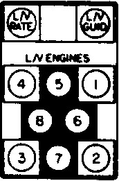
Full-sized crop from the Apollo 4 main display, above.
The L/V ENGINES subpanel was part of the display's "launch vehicle lights" display. Along the top of this display were the L/V RATE light (which glowed red if launch vehicle angular rates were excessive, a condition which could automatically initiate an abort) and the L/V GUID light (which glowed red to indicate a failure in the launch vehicle guidance system, which could also result in an abort).
The L/V ENGINES subpanel contained lights, arranged in the same pattern as the engines on the launch vehicle, with four engines arranged in a center diamond with four additional engines arranged in an outer square. These lights would glow yellow before ignition and would go out once an engine reached 90% thrust. If any engine were to drop blow 90% nominal thrust, the corresponding light would re-light. Unlike the other two lights, an "engine out" light did not initiate an immediate abort; even a second engine light was not necessarily a cue for an immediate abort: Depending upon the time of the failure(s), the launch vehicle had a limited ability to continue the mission.
The L/V ENGINES lights also provided indication of staging; during normal first stage cutoff, the lights would come back on to indicate engine cutoff and would go off again to signal physical separation of the stages. The no. 1 light would come on again at S-IVB ignition and then go off when the S-IVB's J-2 exceeded 65% of nominal thrust.
At the time the Block I command modules were designed and constructed, NASA planned to launch manned Block I CSM missions on production Saturn I rockets. Although these manned Saturn I missions were reprogrammed to instead be flown on Saturn IBs in October 1963, the Saturn IB used an largely-similar first stage as the Saturn I with an identical first stage engine pattern. (The Apollo 1 fire finally eliminated all manned missions in Block I spacecraft.)
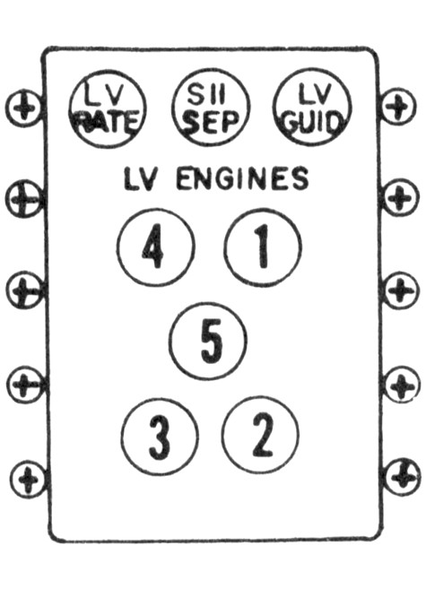
Apollo 4, of course, launched on a Saturn V. The Saturn V-style launch vehicle lights looked like this:

Full-sized crop from my Apollo Command Module Main Display (Apollo 13).
This version of the panel added an SII SEP light, which glowed white when S-IC/S-II staging was initiated and went out when the S-II interstage skirt dropped away from the S-II after ignition. As with the Saturn I/IB-style panel, the LV ENGINES lights were arranged in the same pattern as the first (and second) stage engines; the Saturn V first stage, of course, had five engines instead of the Saturn I/IB's eight.
I thought it odd that the main display diagram showed Apollo 4 with a Saturn I/IB-style L/V ENGINES panel, given that it launched on a Saturn V. My first thought was that a standard Block I command module control panel drawing was used as a base from which to produce this diagram. Then I wondered whether any time or money would have been expended to replace the L/V ENGINES panel, given that the spacecraft would fly unmanned.
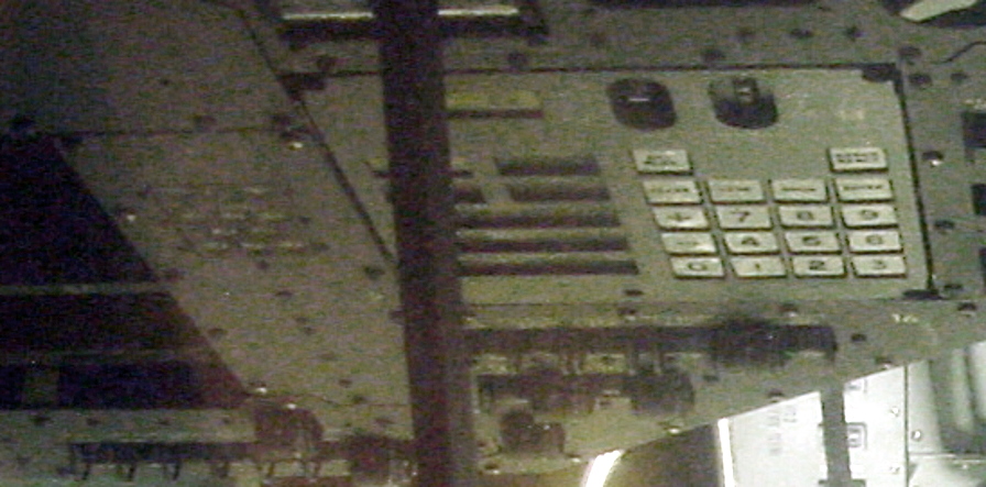
While I did not specifically take any photos of Apollo 4's L/V ENGINES panel, by magnifying and adjusting the brightness of one of the photos I did take, I could verify that Apollo 4 did, indeed, fly with a Saturn I/IB-style L/V ENGINES panel:

Magnified, post-processed crop of dsc09571.jpg from my Apollo 4 photo set at Stennis Space Center.


