| Prev |
heroicrelics.org Recovered F-1 Engine Conservation Site Index Injectors Gallery |
Next |
dsc98384.jpg
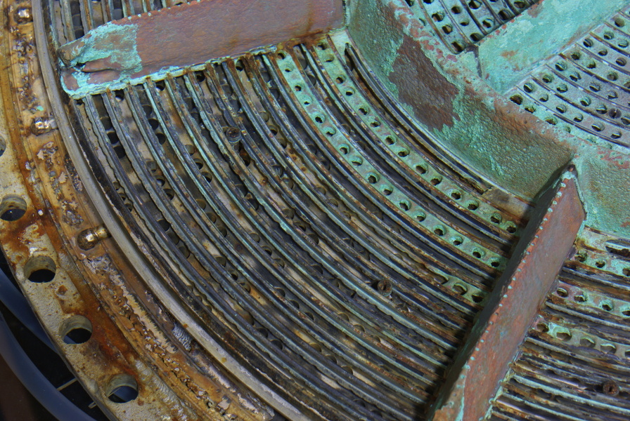
Detail of the first injector.
Picture 2 of 4.
Many of the copper rings comprising the face of the injector have been knocked loose, showing underlying ring grooves. The injector face is made up of alternating rings which spray either fuel or oxidizer. The holes in the rings (still visible near closer to the center of the injector) are arranged in "impinging pairs," which spray streams of propellant toward each other, atomizing the propellant to promote combustion.
The outer-most ring (with the sets of three smaller-diameter holes) is a fuel ring, as is every other ring, alternating with oxidizer rings. The holes in the base of the fuel rings are supplied by fuel feed passages in the side of the injector. The holes in the base of the oxidizer rings are supplied by holes in the injector's forward face; the LOX dome fills the volume between its aft face and the forward face of the injector with liquid oxygen, supplying these holes.
The three short tubes at left in this photo are part of the hypergol manifold and feed the igniter fuel housings.
Two igniter fuel housings (which look a bit like standard screw heads) are visible above and below center of this photo. During engine ignition, a fluid which is pyrophoric (ignites spontaneously in the presence of oxygen) called triethyl aluminum-triethyl borane is sprayed through these housings. The TEA-TEB mixes with the atomized LOX already present in the combustion chamber, igniting. Fuel soon flows through the injector, igniting and sustaining the combustion.
A third igniter fuel housing is visible at lower right.

| Time picture taken | Thu Dec 5 12:07:08 2013 |
| Location picture taken |
Warehouse Floor Cosmosphere SpaceWorks Facility Hutchinson, KS |
| Prev |
heroicrelics.org Recovered F-1 Engine Conservation Site Index Injectors Gallery |
Next |