| Prev |
heroicrelics.org U.S. Space & Rocket Center Site Index O2/H2 Burner (Helium Heater) Gallery |
Next |
dsc66784.jpg
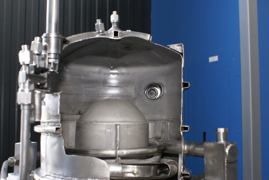
Detail of the forward end of the combustion chamber.
Injector no. 1 appears at left.
Referring to the diagram on my info page, the hole toward the right (above the dome in the center of the combustion chamber) is injector no. 2.
It's harder to tell from the diagram, but it appears that the rectangular valve and associated tubing passing through the combustion chamber at lower right is the hydrogen line; the LH2 inlet is opposite side of the helium heater; the LH2 passes through regenerative coils (presumably the larger-diameter coils) in the interior of the combustion chamber to be heated prior to injection.

| Time picture taken | Fri Jul 10 11:01:22 2009 |
| Location picture taken |
Saturn V Hall Davidson Center for Space Exploration U.S. Space & Rocket Center Huntsville, AL |
| Prev |
heroicrelics.org U.S. Space & Rocket Center Site Index O2/H2 Burner (Helium Heater) Gallery |
Next |