| Prev |
heroicrelics.org U.S. Space & Rocket Center Site Index Lunar Module Mockup Gallery |
Next |
dscc6764.jpg
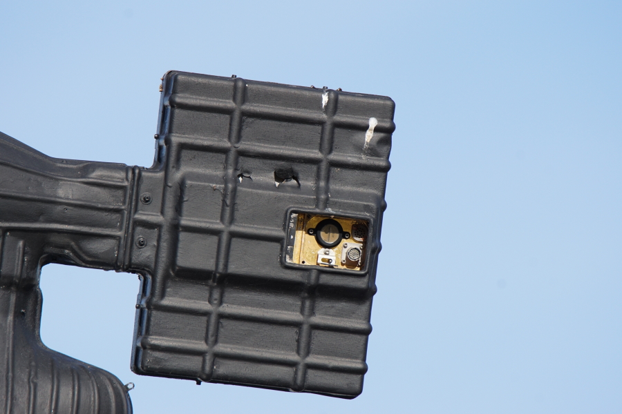
Detail into an open panel in the S-Band steerable antenna's electronics package.
The panel reveals, counter-clockwise from upper left, some sort of gauge or meter (round; gold face with a black border; the left-hand side is marked with "0", "2", "and "4" with marks much like a ruler; the right-hand side is marked with "4000"); a toggle switch with a silver, bent sheet metal switch guard; a female, 19-pin electrical connector; and a dark circular component with two concentric circles of holes drilled in it. The upper right component looks a lot like a female electrical connector, but there are no obvious pin receptacles or any way for a male connector to attach.
Picture 2 of 3.
| Time picture taken | Sat Nov 5 09:47:30 2016 |
| Location picture taken |
Rocket Park U.S. Space & Rocket Center Huntsville, AL |
| Prev |
heroicrelics.org U.S. Space & Rocket Center Site Index Lunar Module Mockup Gallery |
Next |