| Prev |
heroicrelics.org U.S. Space & Rocket Center Site Index V-2 Engine (Old Museum) Gallery |
Next |
dsc10052a.jpg
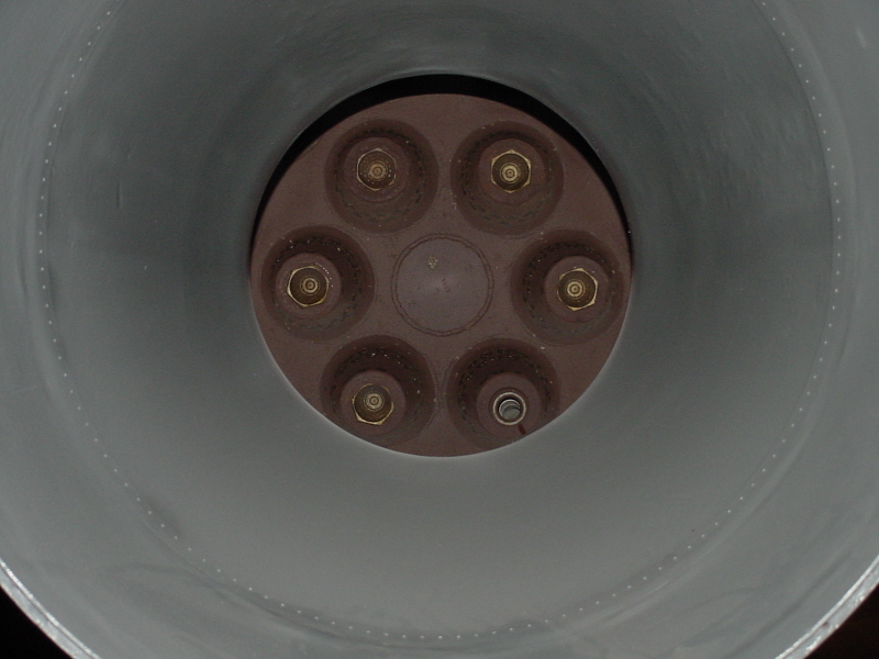
View of the interior of the combustion chamber.
At center is the forward end of the combustion chamber; the interior of six of the burner cups are visible.
Liquid oxygen from the turbopump are routed to the 18 burner cups; the LOX is sprayed into the burner cup via the gold nozzle at the center of each cup.
Fuel from the turbopump is delivered to the alcohol inlets near the thrust chamber's exit plane. The combustion chamber is double-walled; the fuel flows between the two walls, providing regenerative cooling, to the forward end of the combustion chamber, where it flows through the three rows of fuel injectors on the interior of the burner cups, mixing with the LOX and burning.
Several inches forward of the exit plane, also note the holes drilled in the inner wall of the thrust chamber. The regenerative cooling alone wasn't enough to prevent burn-through of the chamber walls, so fuel from four such rows of holes was used to provide film cooling.
| Time picture taken | Fri Jun 17 14:21:25 2005 |
| Location picture taken |
Space Hall "Old" Museum U.S. Space & Rocket Center Huntsville, AL |
| Prev |
heroicrelics.org U.S. Space & Rocket Center Site Index V-2 Engine (Old Museum) Gallery |
Next |