| Prev |
heroicrelics.org U.S. Space & Rocket Center Site Index F-1 Engine F-4028 (Outdoors) Gallery |
Next |
dsc03367.jpg
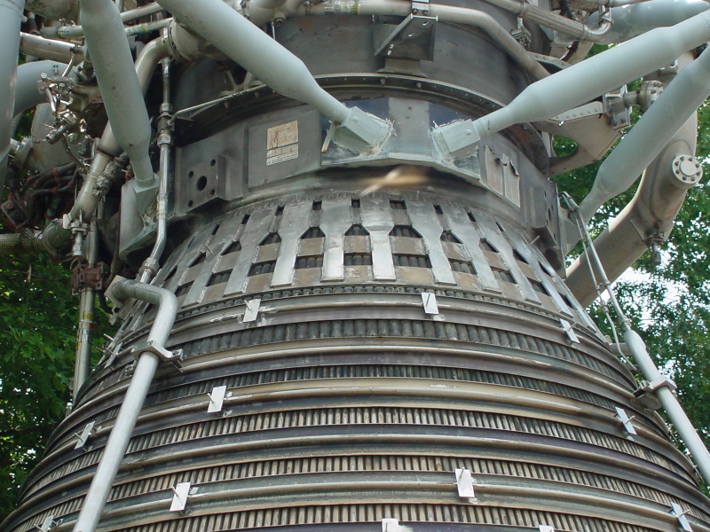
Detail of the forward portion of the thrust chamber.
At the top of this picture are the aft portions of gimbal outriggers.
Below the gimbal outriggers are the throat straps. There are 35 of these which are mounted on flat bands just aft of the engine's throat, presumably to reinforce this area the thrust chamber.
Aft of those are hatbands which help hold the thrust chamber together.
Note the top-most hatband bearing studs to mount the thermal insulation set. Under the next hatband aft (the one with the mounts for the overboard drain lines) the tubes comprising the thrust chamber bifurcate, or split in two; note the relative diameter of the tubes.
This bifurcation can be better seen on the interior of the F-1 engine.
| Time picture taken | Fri Jun 20 11:37:24 2003 |
| Location picture taken |
Rocket Park U.S. Space & Rocket Center Huntsville, AL |
| Prev |
heroicrelics.org U.S. Space & Rocket Center Site Index F-1 Engine F-4028 (Outdoors) Gallery |
Next |