| Prev |
heroicrelics.org U.S. Space & Rocket Center Site Index F-1 Engine F-6045 (Space Hall) Gallery |
Next |
dsc10061a.jpg
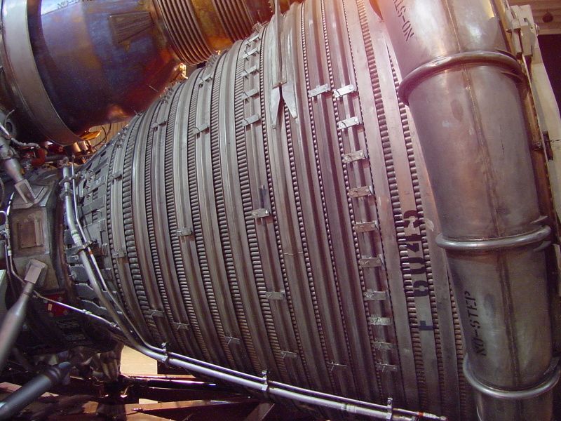
The side of the F-1 engine.
Note the bifurcation joint, where each regenerative cooling tube splits into two, just forward of the heat exchanger bellows.
Also note the tabs and studs welded to the hatbands; these would be used to support the thermal insulation blankets.
| Time picture taken | Fri Jun 17 14:24:59 2005 |
| Location picture taken |
Space Hall "Old" Museum U.S. Space & Rocket Center Huntsville, AL |
| Prev |
heroicrelics.org U.S. Space & Rocket Center Site Index F-1 Engine F-6045 (Space Hall) Gallery |
Next |