| Prev |
heroicrelics.org U.S. Space & Rocket Center Site Index F-1 Engine F-6045 Gallery |
Next |
dsc85319.jpg
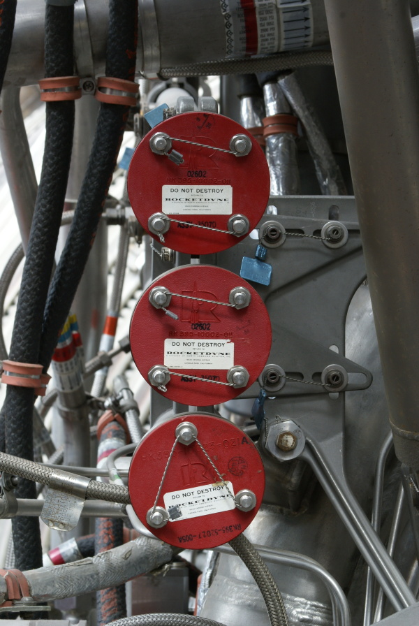
View of three of the lines leading between the heat exchanger and the forward end of the engine.
Picture 6 of 6.
One line, the LOX supply line, is not visible in this photo.
The three other lines run parallel to each other, terminating at these red closures. The lines would connect to the S-IC stage at this point. From top to bottom, these three are the GOX return line, the helium return line, and the helium supply line.
The top two plate assemblies are identical, with four bolts, and having some black stamped numbers, an embossed part number, and a black stamped assembly number:
02602
RK395-10002-011
ASSY - 35070
The bottom plate assembly has three bolts and has both an embossed part number (modified with a black stamped "A") and a black stamped part number (I was unable to find a description of the second part number):
RK395-10023-021A [the "A" is a black stamp]
RK395-52027-005A

| Time picture taken | Fri Jul 20 16:01:02 2012 |
| Location picture taken |
Saturn V Hall Davidson Center for Space Exploration U.S. Space & Rocket Center Huntsville, AL |
| Prev |
heroicrelics.org U.S. Space & Rocket Center Site Index F-1 Engine F-6045 Gallery |
Next |