| Prev |
heroicrelics.org U.S. Space & Rocket Center Site Index F-1 Engine F-6045 Gallery |
Next |
dsc82469.jpg
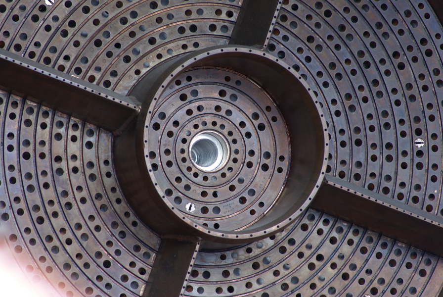
View of the center circular baffle on the injector.
Picture 3 of 3.
The center circular baffle is taller than the outer circular baffle.
Note the threaded hole at center for the thrust chamber throat security closure shaft.
If you look closely at the holes in the injector, you can see that they were drilled at an angle to provide like-on-like impingement, and that the fuel orifices are larger than the oxidizer orifices.
The silver circles which look like flat-head screw heads are igniter fuel housings. The F-1 Rocket Engine Technical Manual: Engine Data (R-3896-1) describes how two igniter fuel housings are located in each of the 12 outer compartments and one in the center compartment. Fed by individual igniter fuel feed tubes from the igniter manifold, they injected igniter fuel into the compartments. The igniter fuel (from the hypergol manifold) was composed of 85% triethylborane and 15% triethylaluminum, and ignited upon contact with oxygen, causing spontaneous combustion and establishing thrust chamber ignition.

| Time picture taken | Sun Jun 3 13:15:28 2012 |
| Location picture taken |
Saturn V Hall Davidson Center for Space Exploration U.S. Space & Rocket Center Huntsville, AL |
| Prev |
heroicrelics.org U.S. Space & Rocket Center Site Index F-1 Engine F-6045 Gallery |
Next |