| Prev |
heroicrelics.org U.S. Space & Rocket Center Site Index F-1 Engine F-6045 Gallery |
Next |
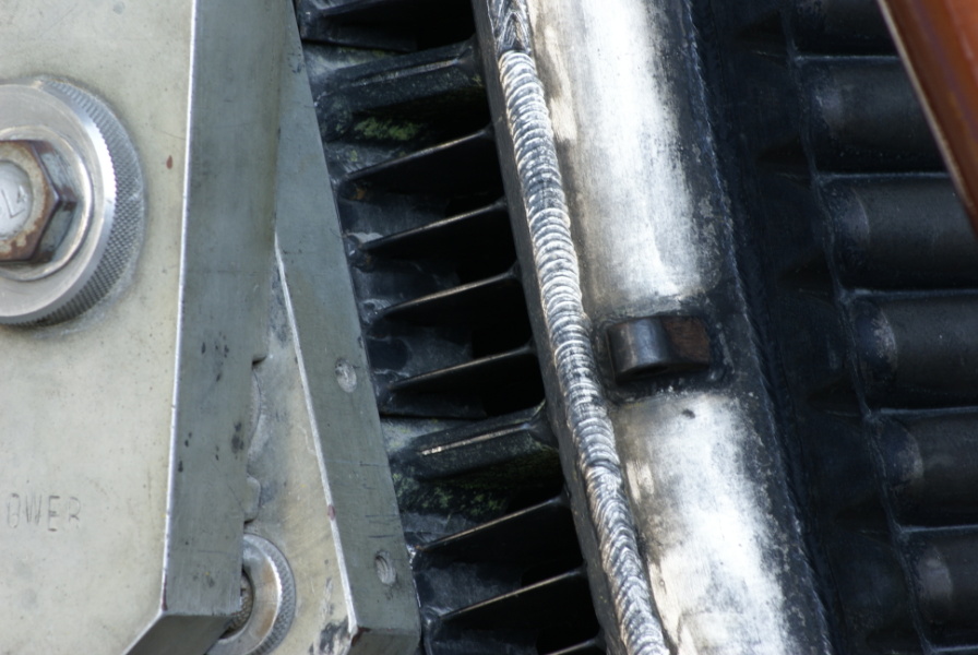
dsc59896.jpg
Detailed views of the fuel return manifold and turbine exhaust manifold flow vanes.
Picture 3 of 3.
Fuel flowed down two adjacent tubes, cooling the engine wall (known as "regenerative cooling"). It reached the fuel return manifold (the silver ring at the exit plane of the thrust chamber), where it returned through two "up" tubes, reaching the fuel manifold and then being injected into the combustion chamber.
The turbine exhaust gases exited through these flow vanes on the aft end of the turbine exhaust manifold, entered the double-walled nozzle extension, and finally entered the main exhaust flow through gaps in the shingles comprising the nozzle extension inner wall, thus providing film cooling to the nozzle extension.
| Time picture taken | Sat Feb 21 12:40:24 2009 |
| Location picture taken |
Saturn V Hall Davidson Center for Space Exploration U.S. Space & Rocket Center Huntsville, AL |
| Prev |
heroicrelics.org U.S. Space & Rocket Center Site Index F-1 Engine F-6045 Gallery |
Next |