| Prev |
heroicrelics.org Stafford Air & Space Museum Site Index LR-87 Engines Gallery |
Next |
dsc46477.jpg
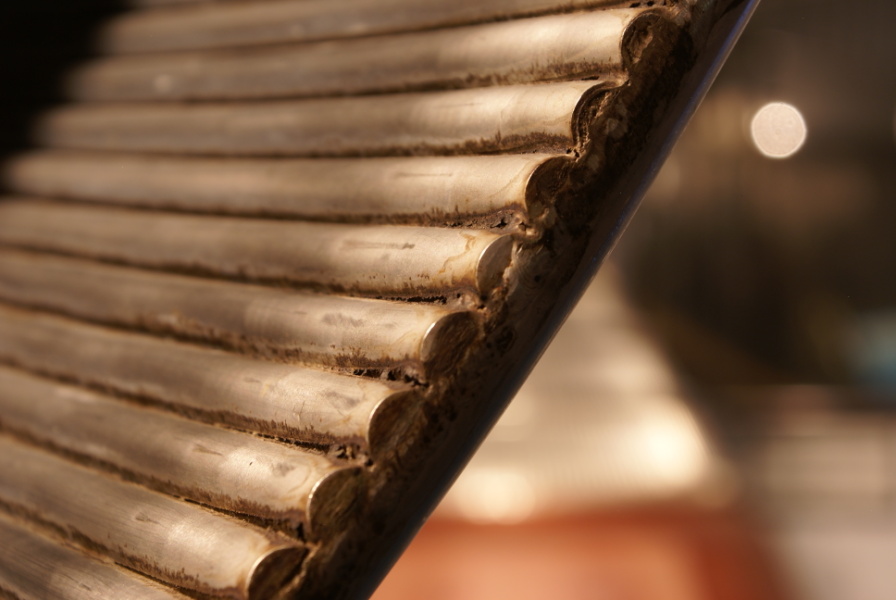
Various views of the regenerative cooling tubes making up the engine's thrust chamber.
Picture 4 of 7.
Detail of the regenerative cooling tube return manifold.
In a regenerative thrust chamber cooling design, fuel is typically pumped down every other tube. When it arrives at the bottom "lip" of the thrust chamber, it enters a return manifold where the fuel is then routed up the other tube and then sent to the combustion chamber.
For a detail of the return manifold on the exterior of the thrust chamber, see dsc46473.jpg.
| Time picture taken | Thu Jul 31 10:04:48 2008 |
| Location picture taken |
Mercury/Gemini Gallery Stafford Air & Space Museum Weatherford, Oklahoma |
| Prev |
heroicrelics.org Stafford Air & Space Museum Site Index LR-87 Engines Gallery |
Next |