| Prev |
heroicrelics.org Space Center Houston Site Index Lunar Test Article 8 (LTA-8) Gallery |
Next |
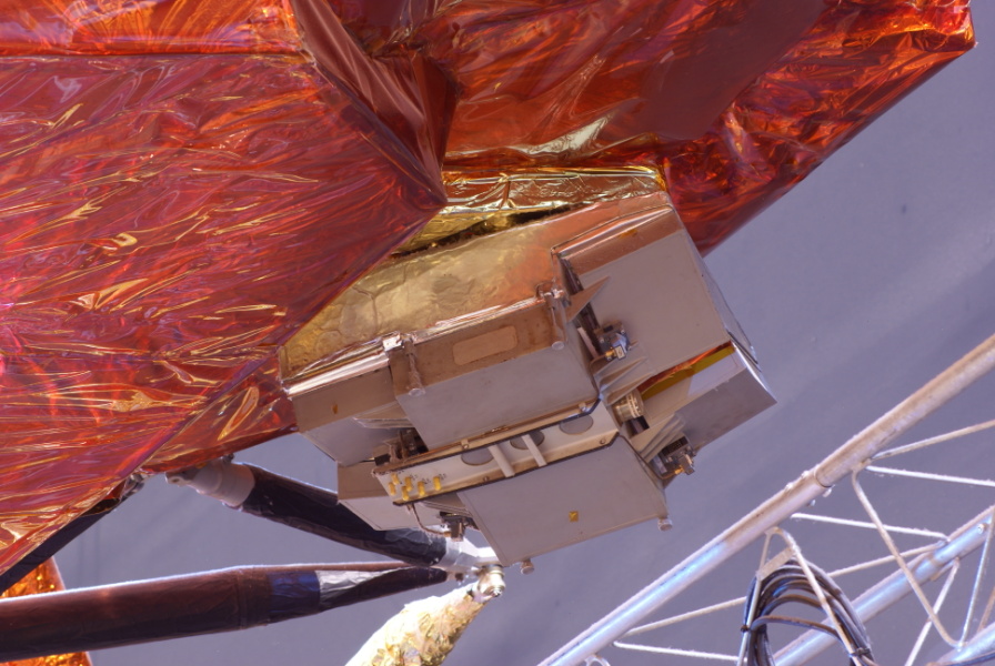
dsc50016.jpg
Overall view of the landing radar antenna. The antenna on LTA-8 visually differs from that on flight models, although I suppose it could simply be that LTA-8's radar antenna lacks the panels comprising the outer cover.
As described by the Lunar Module News Reference,
The landing radar senses the velocity and slant range of the LM relative to the lunar surface by means of a three-beam Doppler velocity sensor and a single-beam radar altimeter. Velocity and range data are made available to the LM guidance computer ...
The landing radar consists of an antenna assembly and an electronics assembly. The antenna assembly forms, directs, transmits, and receives the four microwave beams. Two interlaced phased arrays transmit the velocity- and altimeter-beam energy. Four broadside arrays receive the reflected energy of the three velocity beams and the altimeter beam. The electronics assembly processes the Doppler and continuous-wave FM returns, which provide the velocity and slant range data for the LM guidance computer and the LM displays.
The antenna assembly transmits velocity beams (10.51 gHz) and an altimeter-beam (9.58 gHz) to the lunar surface.
The radar is first turned on and self-tested during LM checkout before separation from the CSM. ... The radar is self-tested again immediately before LM powered descent, approximately 70,000 feet above the lunar surface. The radar operates from approximately 50,000 feet until lunar touchdown.
Altitude (derived from slant range) is available to the LGC and is displayed on a cabin indicator at or above 25,000 feet. Slant range data are continuously updated to provide true altitude above the lunar surface. At, or above 18,000 feet, forward and lateral velocities are available to the LM guidance computer and cabin indicators.
The [antenna] assembly comprises four microwave mixers, four dual audio-frequency preamplifiers, two microwave transmitters, a frequency modulator, and an antenna pedestal tilt mechanism. The antenna consists of six planar arrays: two for transmission and four for reception. They are mounted on the tilt mechanism beneath the descent stage, and may be placed in one of two fixed positions.
Picture 1 of 2.
| Time picture taken | Mon Aug 4 09:42:30 2008 |
| Location picture taken |
Outside Starship Gallery Space Center Houston Houston, TX |
| Prev |
heroicrelics.org Space Center Houston Site Index Lunar Test Article 8 (LTA-8) Gallery |
Next |