| Prev |
heroicrelics.org Space Center Houston Site Index Lunar Test Article 8 (LTA-8) Gallery |
Next |
dsc50004.jpg
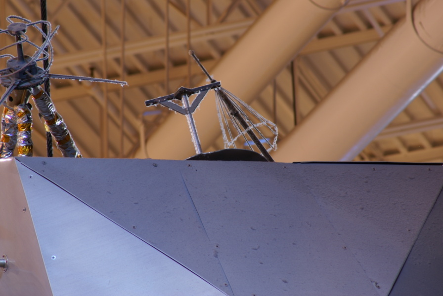
Detail of the rendezvous docking target (the T-shaped device at center).
As described by the Lunar Module LM-10 Through LM-14 Vehicle Familiarization Manual:
The docking target permits docking to be accomplished on a three-dimensional alignment basis. The target consists of an inner circle and a standoff cross of black with self-illuminating disks within an outer circumference of white. The target-base diameter is 17.68 inches. The standoff cross is centered 15 inches higher than the base and, as seen at the intercept, is parallel to the X-axis and perpendicular to the Y-axis and the Z-axis.
During transposition, docking, and extraction (removing the lunar module from the spacecraft/lunar module adapter (SLA)), the command module pilot would use a Crewman Optical Alignment Sight to align the command module with the lunar module. Page 9 (page 11 in the PDF) of the Full-Size Pilot-Controlled Docking Simulation of the Apollo Command and Service Module with the Lunar Module contains a series of photos showing how the docking target was used during this phase of the mission.
NASA photo AS11-36-5365 shows the docking target from the CMP's perspective.
Also visible in this photo are the cone-shaped VHF EVA antenna (behind and to the right of the docking target) and the forward VHF antenna (used to communicate with the command module).
| Time picture taken | Mon Aug 4 09:35:30 2008 |
| Location picture taken |
Outside Starship Gallery Space Center Houston Houston, TX |
| Prev |
heroicrelics.org Space Center Houston Site Index Lunar Test Article 8 (LTA-8) Gallery |
Next |