| Prev |
heroicrelics.org Michigan Space and Science Center Site Index Apollo LM-Active Docking Target Gallery |
Next |
dsc02370.jpg
An LM-active docking target.
Picture 1 of 2.
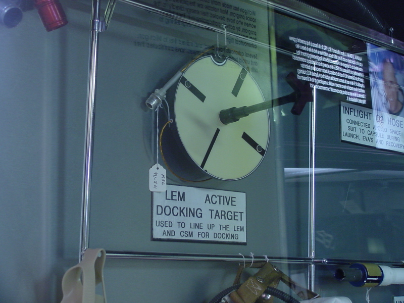
| Time picture taken | Wed Apr 23 13:41:23 2003 |
| Location picture taken |
Michigan Space & Science Center Jackson, MI |
| Prev |
heroicrelics.org Michigan Space and Science Center Site Index Apollo LM-Active Docking Target Gallery |
Next |