
V-2 Cutaways
This page serves as a repository for cutaway diagrams and photos of the V-2/A-4.
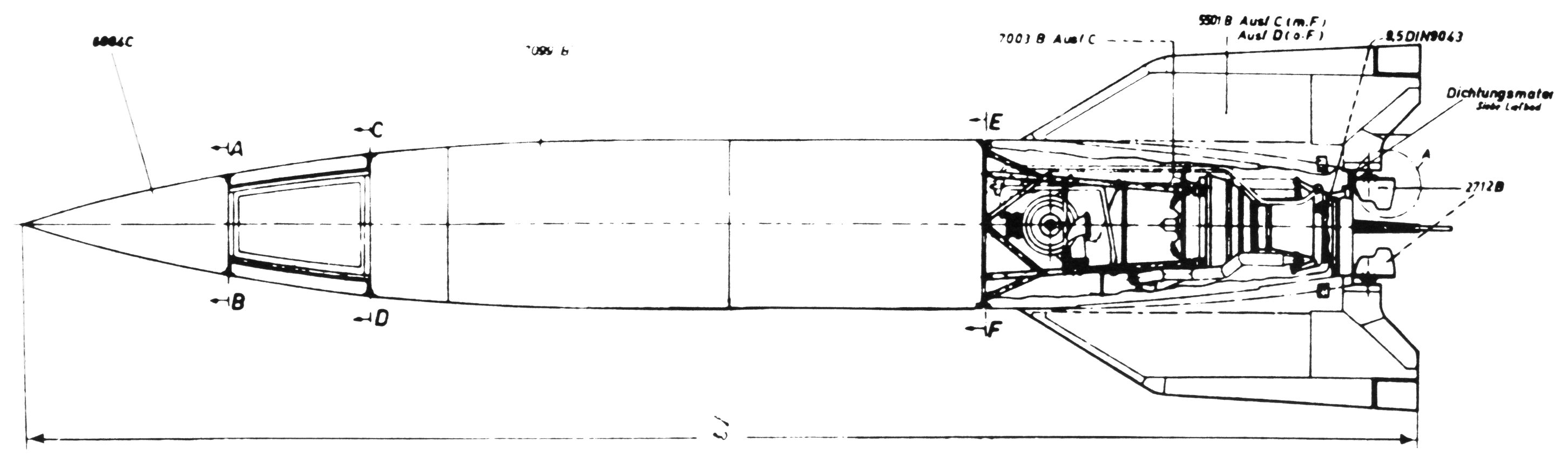
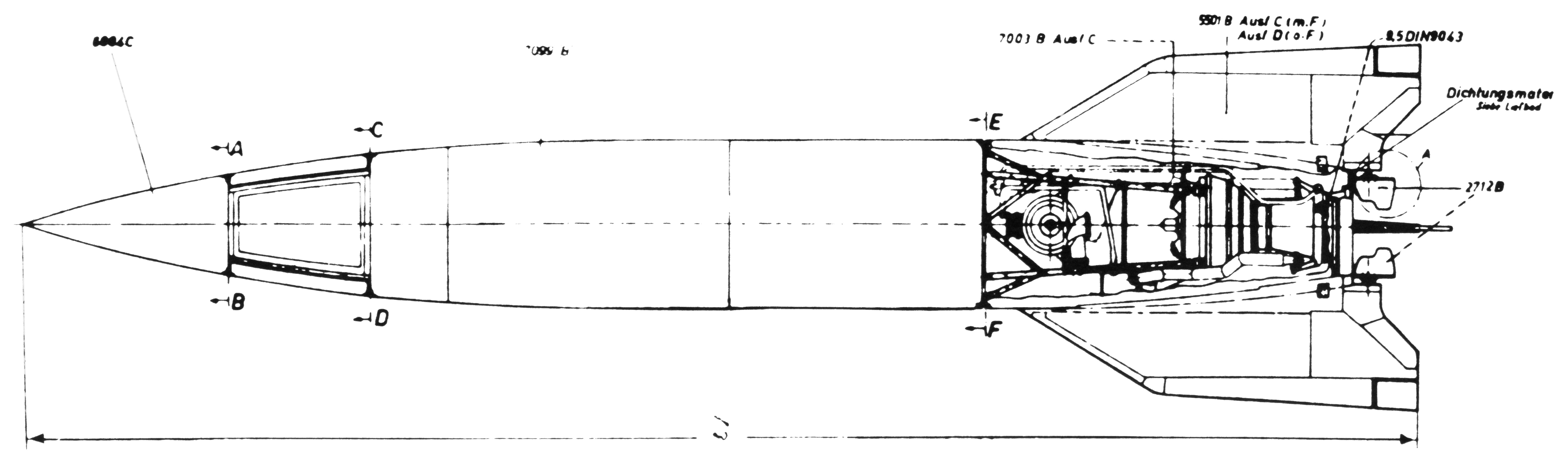
This diagram shows a cutaway of the engine compartment. The instrumentation compartment, outlined by the "A-B-C-D" just aft of the warhead, is not cut away in this diagram, but the access panels are open on the V-2 at the Kansas Cosmosphere.
Click image for a 2904x858 pixel version of this image in a new window or
click here for a 5808x1716
pixel version of this image in a new window.
From the front cover of Technical Data on the Development of the
A4/V-2, located in the private collection of Dave Christensen (also available from the
NASA Technical Reports Server; alternate
link).
Scan and restoration by heroicrelics.
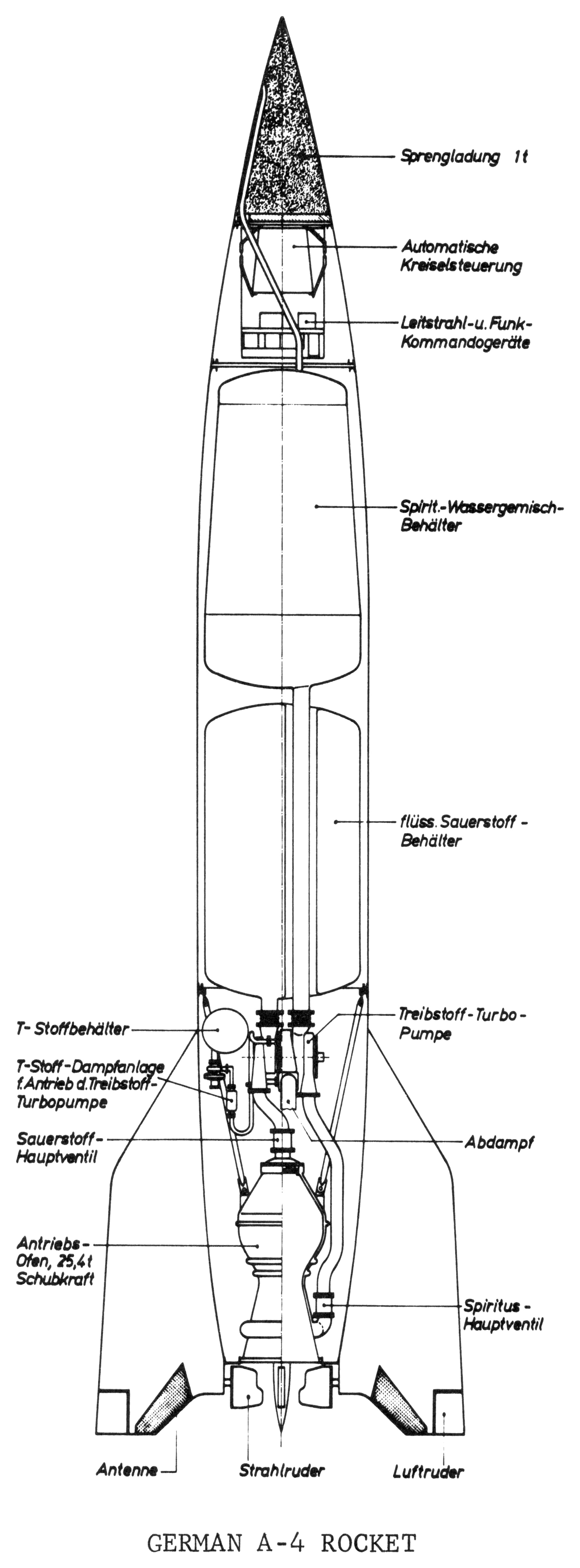
Here's a nice cutaway with call-outs:

Click image for a 905x2446 pixel version of this image in a new window or
click here for a 1810x4891
pixel version of this image in a new window.
From the page 26 of Technical Data on the Development of the
A4/V-2, located in the private collection of Dave Christensen (also available from the
NASA Technical Reports Server; alternate
link).
Scan and clean-up by heroicrelics.
Callouts:
- Sprengladung 1t (1-Ton Explosive Charge)
- Automatische Kreiselsteuerung (Automatic Gyro Control)
- Leitstrahl-u. Funk-Kommandogeräte (Guidebeam and Radio Command Receivers)
- Spiritus-Wasser Gemisch Behälter (Alcohol-Water Mixture Tank)
- flüss. Sauerstoff-Behälter (Liquid Oxygen Tank)
- Treibstoff Turbo-Pumpe (Fuel Turbopump)
- Abdampf (Turbine [Steam] Exhaust)
- Spiritus-Hauptventil (Main Alcohol Valve)
- Luftruder (Aerodynamic Rudder)
- Strahlruder (Graphite Rocket Engine Exhaust Vane)
- Antenne (Antenna)
- Antriebs-Ofen, 25,4t Schubkraft (Rocket Engine, 25.4 Tons of Thrust)
- Sauerstoff-Hauptventil (Main Oxygen Valve)
- T-Stoff-Dampfanlage f. Antrieb d. Treibstoff-Turbopumpe (Hydrogen Peroxide Steam Generator for Driving the Turbopumps)
- T-Stoffbehälter (Hydrogen Peroxide Tank)
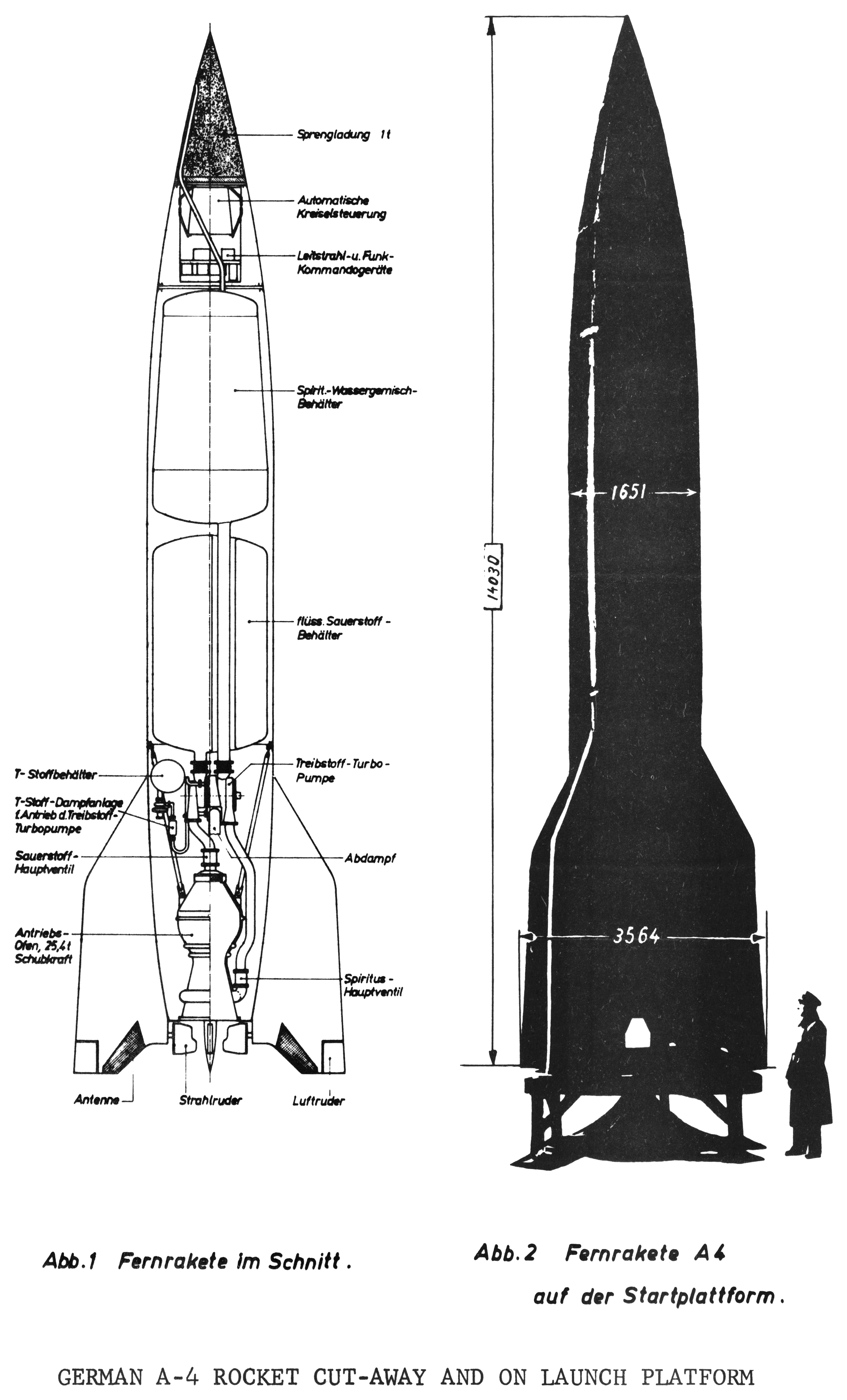
I pointed out how nice the cutaway V-2 diagram above was; the document's authors thought it was so nice that they decided to reuse it, not once, but twice!
Here the cutaway diagram is used to compare with the missile on the launcher platform:

Left caption: Cross-section of Long Range Rocket
Right caption: Long Range Rocket on Launch Table
Click image for a 984x1627 pixel version of this image in a new window or
click here for a 2952x4881
pixel version of this image in a new window.
From page 27 of Technical Data on the Development of the A4/V-2,
located in the private collection of Dave Christensen (also available from the
NASA Technical Reports Server; alternate
link).
Scan and clean-up by heroicrelics.
Back in the 1940s, the 200-mile range V-2 was considered a "Fernrakete", or "long-range" rocket, while today 200 miles barely qualifies as a "short-range" missile.
Here the cutaway diagram is used to compare the A-4 against its predecessors, the A-3 and the A-5:

Click image for a 1005x1509 pixel version of this image in a new window or
click here for a 3551x5030
pixel version of this image in a new window.
From page 25 of Technical Data on the Development of the A4/V-2,
located in the private collection of Dave Christensen (also available from the
NASA Technical Reports Server; alternate
link).
Scan and clean-up by heroicrelics.
Here's a series of drawings which would seem to all be based on the same original, yet are all slightly different.
The first was appeared in a report prepared for the U.S. government shortly after the war by North American Aviation, Inc. During the war NAA made such legendary planes as the P-51 Mustang and the B-25 Mitchell. After the war, they were given V-2 hardware. A division which would go on to become Rocketdyne reverse-engineered the engine, made their own copy, and then went about improving it to create such early engines as the engine for the Navajo cruise missile and the A-7 Redstone. engine.
Click image for a 5518x2855 pixel version of this image in a new window.
From North American Aviation Inc Report No. 46-810, A-4 Propulsion System
Analysis, located in the archives of the U.S. Space & Rocket
Center.
Scan and cleanup by heroicrelics.
This diagram has a few callouts:
- 4 Stabilising Fins
- 4 Internal Control Vanes
- 4 External Control Vanes
- Combustion Chamber and Venturi
- Turbine and Pump Assembly
- Liquid Oxygen Tank
- Alcohol Tank
- Control Compartment
- Warhead
This one was produced by the U.S. Army:
Click image for a 1800x1112 pixel version of this image in a new window.
Scan courtesy the National
Museum of the US Air Force.
Reconstruction by heroicrelics.
In addition to the callouts in the above diagram this one contains many more:
- Chain Drive to External Control Valve
- Electric Motor
- Burner Cups
- Alcohol Supply from Pump
- Air Bottles
- Rear Joint Ring and Strong Point for Transport
- Servo-Operated Alcohol Outlet Valve
- Rocket Shell
- Radio Equipment
- Pipe Leading from Alcohol Tank to Warhead
- Nose Probably Fitted with Nose Switch, or other Device for Operating Warhead Fuze
- Conduit Carrying Wires to Nose or Warhead
- Central Exploder Tube
- Electric Fuze for Warhead
- Plywood Frame
- Nitrogen Bottles
- Front Joint Ring and Strong Point for Transport
- Pitch and Azimuth Gyros
- Alcohol Filling Point
- Double Walled Alcohol Delivery Pipe to Pump
- Oxygen Filling Point
- Concertina Connections
- Hydrogen Peroxide Tank
- Tubular Frame Holding Turbine and Pump Assembly
- Permanganate Tank (Gas Generator Unit Behind this Tank)
- Oxygen Distributor from Pump
- Alcohol Pipes for Subsidiary Cooling
- Alcohol Inlet to Double Wall
- Electro-Hydraulic Servo Motors
- Aerial Leads
I suspect the clerk who typed the captions on this diagram copied them from the diagram below, as there are a few typographical errors and at least one place where a misspelling crept in because of a smudge on the diagram below. The diagram itself also contains the British spelling of "stabilising."
However, this diagram does have an additional detail neither the one above nor below has: This diagram has aerial leads (#30) on the tailing edge of the "stabilising" fins.
Click image for a 3508x2304 pixel version of this image in a new window.
Scan courtesy the Imperial
War Museum.
Cleanup by heroicrelics.
The same basic callouts as above:
- Chain Drive to External Control Valve.
- Electric Motor.
- Burner Cups.
- Alcohol Supply from Pump.
- Air Bottles.
- Rear Joint Ring and Strong Point for Transport.
- Servo-Operated Alcohol Outlet Valve.
- Rocket Shell Construction.
- Radio Equipment.
- Pipe Leading from Alcohol Tank to Warhead.
- Nose Probably Fitted with Nose Switch or other Device for Operating Warhead Fuze.
- Conduit Carrying Wires to Nose or Warhead.
- Central Explorer Tube.
- Electric Fuze for Warhead.
- Plywood Frame.
- Nitrogen Bottles.
- Front Joint Ring and Strong Point for Transport.
- Pitch and Azimuth Gyros.
- Alcohol Filling Point.
- Double Walled Alcohol Delivery Pipe to Pump.
- Oxygen Filling Point.
- Concertina Connections.
- Hydrogen Peroxide Tank.
- Tubular Frame Holding Turbine and Pump Assembly.
- Permanganate Tank (Gas Generator Unit Behind this Tank).
- Oxygen Distributor from Pump.
- Alcohol Pipes for Subsidiary Cooling.
- Alcohol Inlet to Double Wall.
- Electro Hydraulic Servo Motors.
Here's another "skin peeled away" type diagram, as opposed to a line drawing. The photo I scanned appeared to have been a photo of a photo, where the original photo or diagram was not flat; close inspection of my scan shows various areas where the focus is soft.
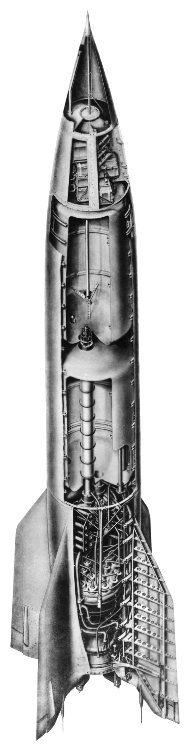
Click image for a 650x2560 pixel version of this image in a new window or
click here for a 2834x11164
pixel version of this image in a new window.
From the green "A-4 Details" binder, "Tech Development A4 by
Schulze" binder, located in the archives of the U.S. Space & Rocket
Center.
Scan and restoration by heroicrelics.
Thanks to Dr. Dieter M. Zube for translation assistance.