
V-1 "Buzz Bomb" Cut-Aways
This page serves as a repository for V-1 cut-away drawings.
Here's an NACA (National Advisory Committee for Aeronautics, a precursor to NASA) drawing from 8-10-44:
Click image for a 3000x2400 pixel version of this image in a new window.
Scan by GRC
ImageNet.
Restoration by heroicrelics.
The National Museum of the U.S. Air Force had a scan of a nice V-1 cut-away drawing (depicting a barrage of V-1s) which was in need of restoration, so I present my restored version here:
Click image for a 1800x1118 pixel version of this image in a new window.
Scan by National
Museum of the United States Air Force.
Restoration by heroicrelics.
This diagram is an old scan (circa 2007). I'm pretty sure I scanned this out of a library book, but since I hadn't started my Website at that time, I was not yet careful at recording my sources.
Click image for a 3417x2246 pixel version of this image in a new window.
Scan and restoration by heroicrelics.
Unlike the diagrams above, this one has callouts for major components:
- Light alloy nose fairing probably containing a compass
- Warhead: Approx. 1000 kg.
- Fuel fillers cap
- Lifting lug
- Launching rail
- Steel tubular main spar passing through fuel tank
- Fuel Tank (Capacity 130 galls. petrol)
- Wirebound spherical compressed air bottles
- Grill incorporating shutters & petrol injection jets
- Pressed steel wing ribs
- Sheet steel wing covering
- Impulse duct engine
- Automatic pilot: 3 airdriven gyros: Height & range settings controls
- Pneumatic servo mechanism operating rudder & elevators
As a cut-out drawing accurately depicting the internal layout of the V-1, it seems odd that the nose fairing is noted as "probably containing [a] compass"; one would think that the artist would know whether a compass was used or not.
This more modern two-view of the V-1, produced by the U.S. Air Force, confirms that the V-1's nose does, indeed, contain a compass:

Click image for a 2116x2990 pixel version of this image in a new window.
From page 36 (p. 53 in the PDF) of We Develop Missiles,
Not Air! The Legacy of Early Missile, Rocket, Instrumentation, and Aeromedical
Research Development at Holloman Air Force Base
Extraction and cleanup by heroicrelics.
Callouts on this diagram include
- Opening for filling gasoline
- Gasoline
- Air Pressure Servo Device
- Air Tanks (Strengthened with steel wire strips)
- Servo Motors for moving rudder and elevators
- Elevators
- Reducer Valve
- Pilot Compass
- Pilot Tube
- Combustion Chamber
- Automatic Pilot
- Controller
- Static Pressure Tube
- Gasoline Strainer
- Contact Box
- Gasoline Regulating Supply Device
This diagram contains the following dimensional information:
- Fuselage length: 7.3 m
- Combustion chamber length: 3.75 m
- Combustion chamber hangs over the end of the fuselage 1.15 m, for an overall length of 8.45 m
- Wingspan: 5.8 m
- Chord length: 1.06 m
- Span of horizontal stabilizers: 2.1 m
- Chord of horizontal stabilizers: 0.38 m
- Chord of elevators: 0.18 m
The German V-1 handbook (scanned at a disappointingly-low resolution) has a cut-away drawing entitled "Anordnung der Steuerung im Gerät" ("Arrangement of Control in the Device"):
From "Teil 2: Steuerung" ("Part 2: Control"), page 6 (p. 52 in the PDF) of FZG 76 Geräte-Handbuch (V-1
Equipment Manual)
Extraction and cleanup by heroicrelics.
Callouts on this diagram include
- Umwandler (Converter/Transducer)
- elektrische Stützstromleitung (Electrical Power Line)
- Druckminderer (Pressure Reducer)
- mech. Gestänge (Mechanical Linkages)
- Rudermaschinen (Rudder Machinery)
- Pneumat. Impulsleitg. (Pneumatic Pressure Line)
- Steuergerät (Control Unit)
- Pressluftbehälter (Pressurized Air Container)
- Betriebsdruckleitung (Operating Pressure Line)
- Kompass (Compass)
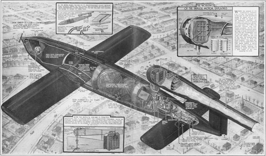
The October 7, 1944 issue of the Illustrated London News had a story called "Secrets of the Flying Bomb Revealed" with the publication's centerfold containing an incredible artist's view of the inner workings of the V-1. A short article contained information about how the V-1 was readied for launch and sent off in the general direction of its target.
Although the publication has long been out of print, the company survives today as a "publishing, content, and digital agency" (which sounds ominous), so I'll not restore and present their diagram but instead link to a very high-resolution scan of the diagram by GermanPostalHistory.com (you may need to scroll down on the resulting Webpage to see the diagram):
Click image to open the diagram's page at GermanPostalHistory.com in a new window.
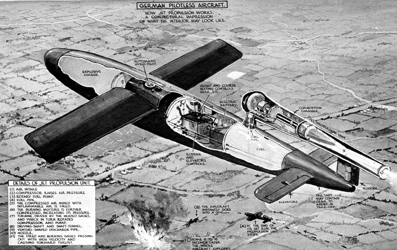
And, finally, an unidentified wartime "conjectural impression of what the interior [of the V-1] may look like." A lot of conjecture was used, but the speculation resulted in nearly every detail of the interior arrangement being wrong: The explosive charge is much larger in this diagram than the actual weapon, the autopilot and course control settings are in the wrong location, the fuel tank is in the wrong location, and the actual V-1's pulsejet is represented as something very similar to a turbojet engine. It even suggest the propulsion unit's cutoff at the end of the flight was intentional, rather than due to a design flaw. (The "nose fairing probably containing compass" conjecture on the diagram up above suddenly seems insightful!)
Although wrong in nearly every aspect other than general external physical appearance, I include this diagram here because it represents an early guess at how a new weapon might work. Also, it's fairly common out on the Internet and I want to clearly label this diagram as wrong.
Click image for a 1306x823 pixel version of this image in a new window.
Taken from the "Drawing, German Pilotless Bomb, What it May Look
Like" link on the Axis History
Forum