
Jupiter-C/Juno High Speed Stages
During the early years of the Space Race, the majority of successfully-launched U.S. satellites (and a goodly number of the U.S. partial successes and launch failures) were sent aloft atop Juno I and Juno II launch vehicles.
Click either image for additional information in a new window.
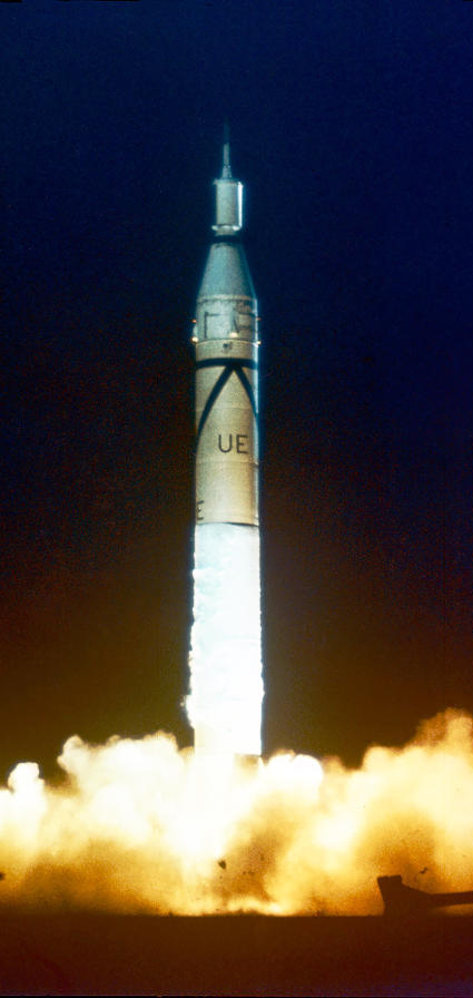
Left: Launch of Juno I, Round 29, with Explorer I as its payload.
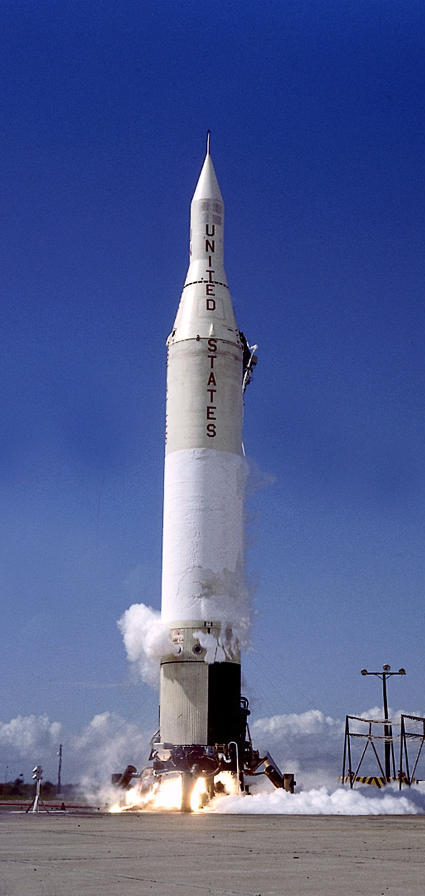
Right: Launch of Juno II AM-19A, with Explorer VII as its payload.
These early satellite launchers were comprised of modified Redstone or Jupiter first stages combined with a set of "high speed stages" designed and manufactured by the Jet Propulsion Laboratory. In its early days, JPL was a military contractor, designing and fabricating "jet propulsion" related products such as jet-assisted take off (JATO) rockets and the U.S. Army's MGM-5 Corporal liquid-fueled and MGM-29 Sergeant solid-fueled intermediate-range ballistic missiles. (JPL was transferred from the Army to NASA after the National Air and Space Administration began operations in October 1958.)
There appears to be little documentation regarding why these upper stages are referred to as "high speed stages". I suspect it is because these stages added the "high speed" to the speed imparted by the Redstone or Jupiter first stage necessary to place its payload into orbit.
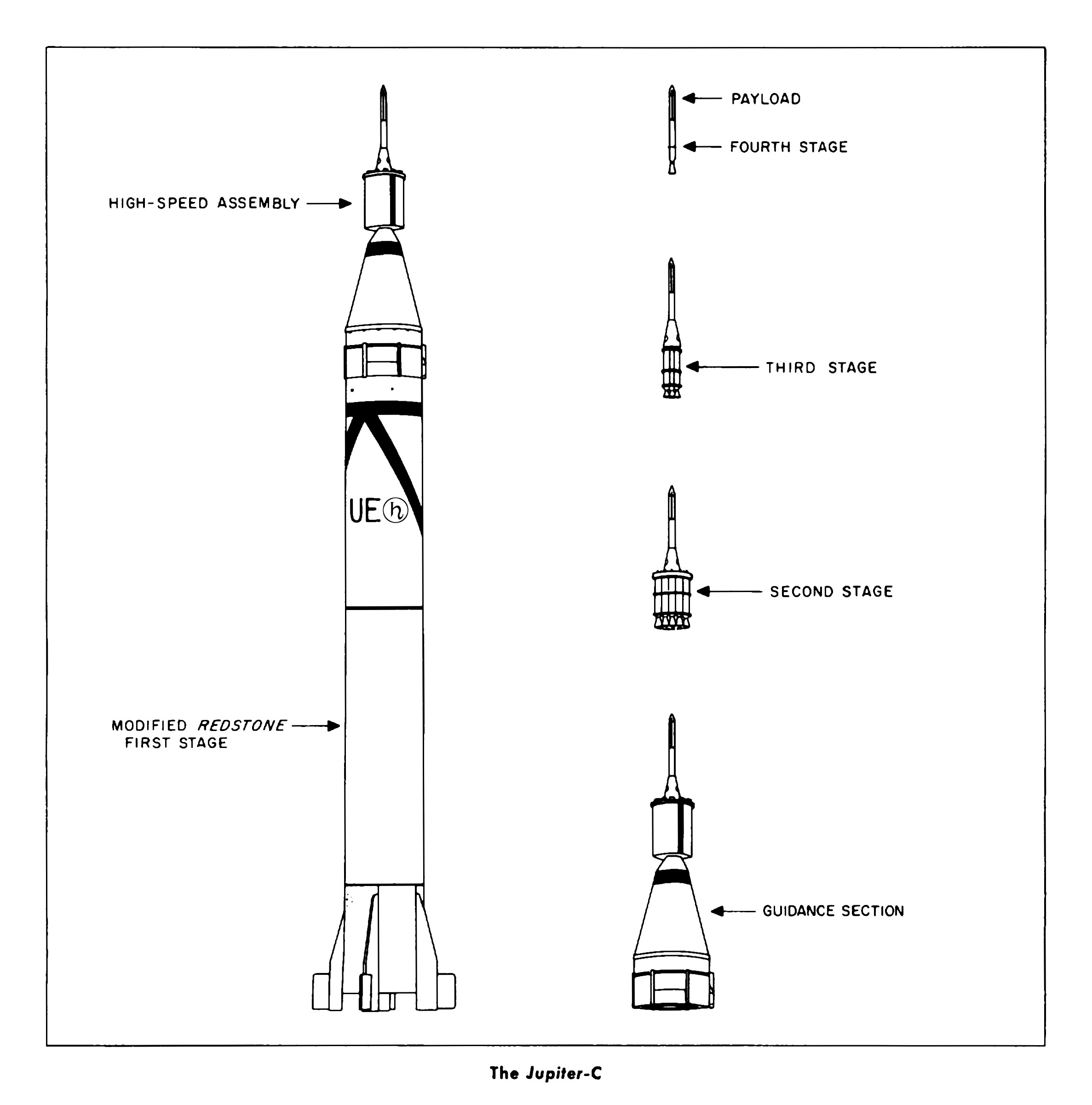
These high speed stages consisted of three stages, each powered by solid rocket motors. JPL had been experimenting with smaller versions of the Sergeant solid rocket motor. While the entire Sergeant missile was 34 and a half feet long and 31 inches in diameter, these scaled Sergeant rocket motors were four feet long and six inches in diameter. JPL had test-fired over 300 of these scaled Sergeant rocket motors (including flight-testing 50 of them), which had proved their reliability.
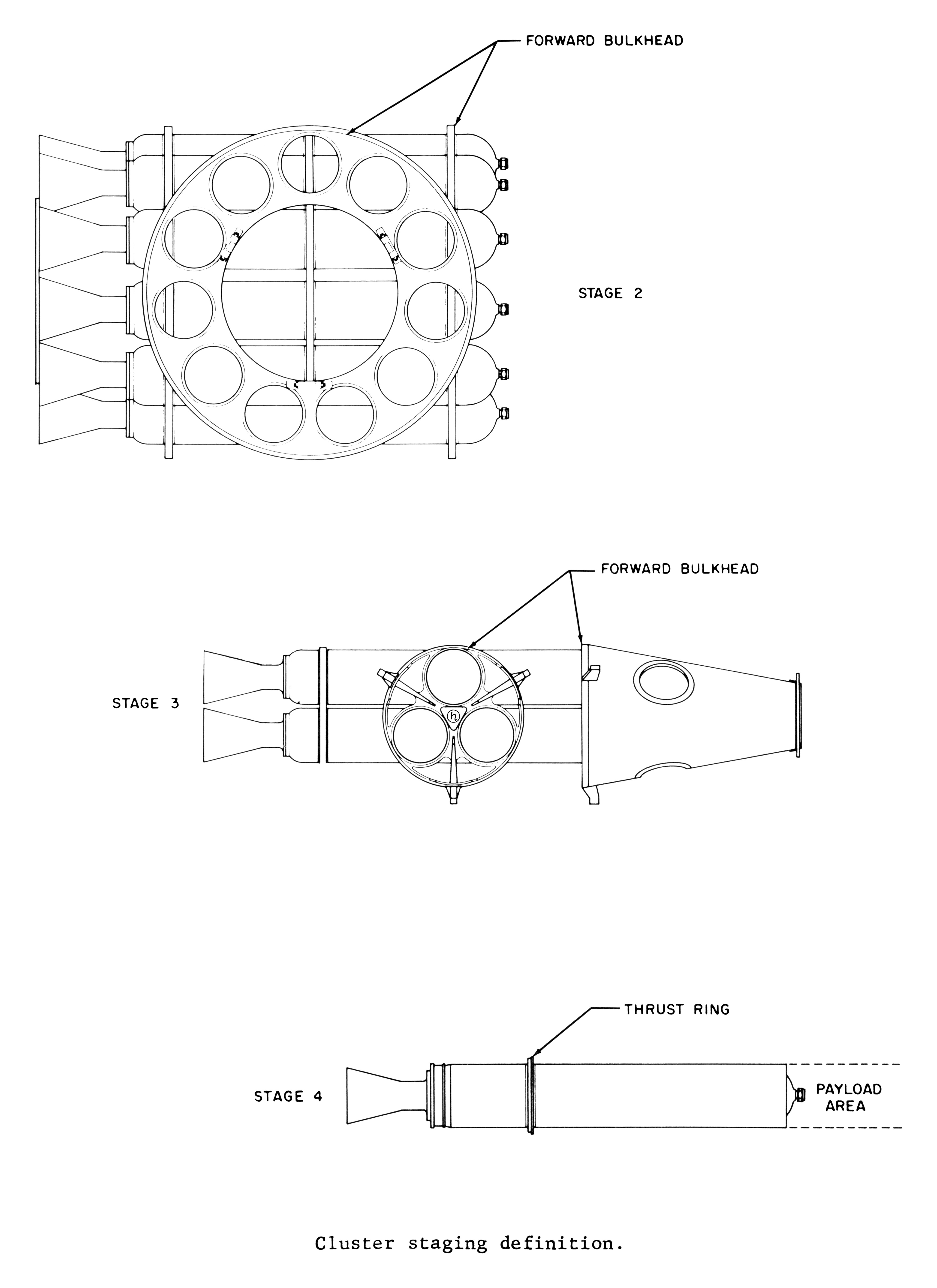
The high speed assembly took the form of a "tub", with the eleven rocket motors of the launcher's second stage being arranged in a cylindrical ring around the periphery of the assembly. Within this annulus was nested the three motors of the third stage. The fourth stage consisted of a single rocket motor, mounted atop a support cone at the forward end of the third stage.
Click image for a 2374x2402 pixel version of this image in a new window.
From page 43 (p. 55 of the PDF) of Juno,
Volume 1: Juno 1: Re-entry Test Vehicles and Explorer
Satellites.
Extraction and cleanup by heroicrelics.org.
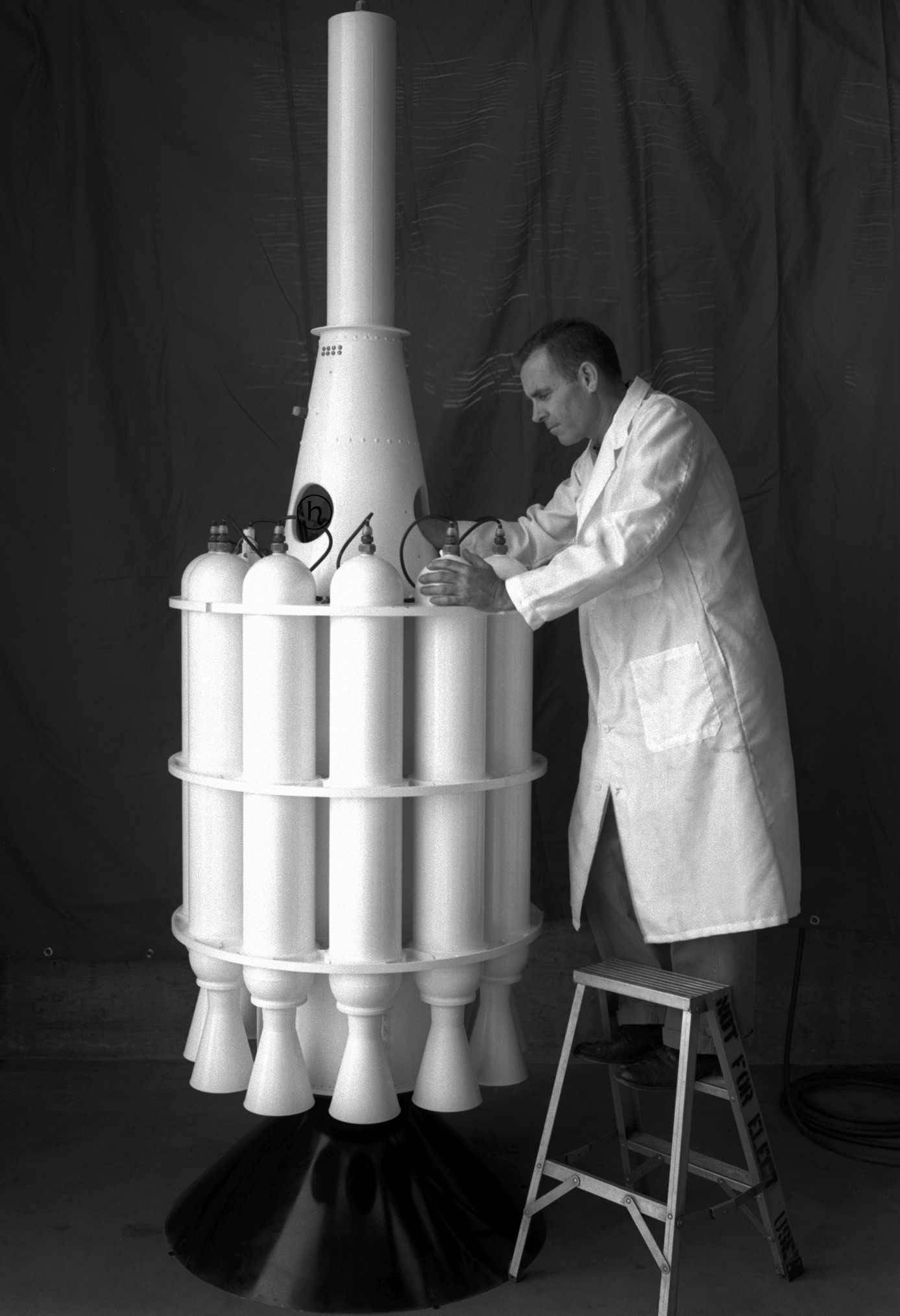
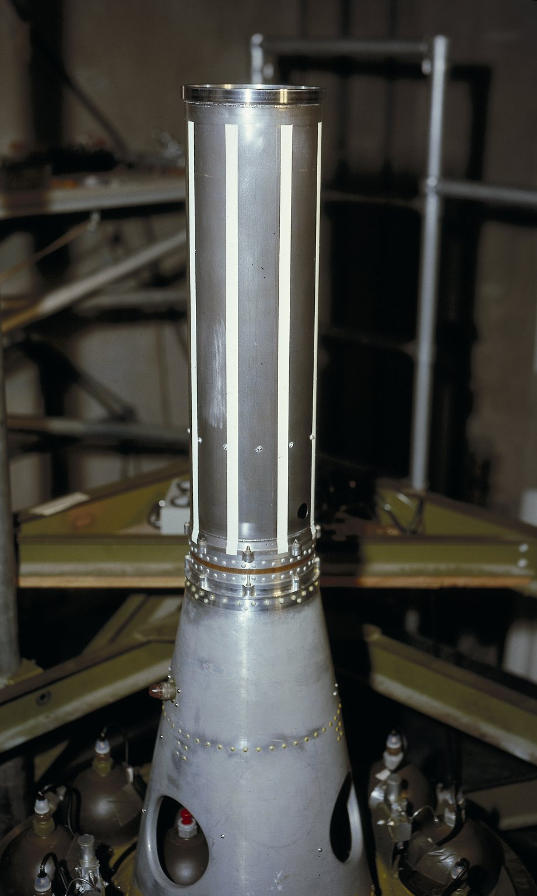
This photo shows the high speed cluster with its outer fairing removed:
Click image for a 1387x2028 pixel version of this image in a new window.
From JPL's now-defunct "Juno
Jupiter Cluster Black and White" page. Note that original photo had
been reversed.
Retrieval and cleanup by heroicrelics.org.
The rocket motors on the second and third stages were identical, with round forward bulkheads. The fourth stage differed slightly, being flat at its forward end to facilitate mating to the payload. For most of the launches (including Explorer 1), the payload remained attached to the fourth stage after the stage was expended. The famous photo of von Braun, van Allen, and Pickering holding a mockup of Explorer 1 over their heads actually shows the satellite itself (with its black and white stripes) attached to the fourth stage (with the motor's nozzle at the end).
This photo of the high speed assembly's fourth stage also shows the fourth stage support cone and (through one of the holes in the adapter) one of the third stage motors. Several motors from the second stage are also visible. It nicely contrasts the forward end of the fourth stage motor casing as compared to the lower stages.
Click image for additional information in a new window.
The high speed assembly from Juno II AM-19B.
The upper stages had no guidance system. To help keep the proper attitude, the entire upper-stage cluster was rotated on its long axis for spin stabilization. This rotation also served to minimize the effects of thrust variations between the individual motors of each stage ("thrust dispersion"). The cluster was spun via two electric motors located in the guidance section of the first stage booster.
On the one hand, spinning the cluster as fast as possible increased accuracy and minimized dispersion. On the other hand, certain spin rates would set up a critical resonance with the first stage which might cause the vehicle to fail from the vibrational loads. The missile's resonance frequency varied as it depleted its propellant during flight.
In order to minimize this resonance problem, the cluster's rotation speed was programmed increase during the flight. While the rotational rate varied from mission to mission, for Explorer 1 the cluster was spun up to 560 rpm prior to liftoff and its spin rate was increased to 751 rpm at 115 seconds into flight.
Click image for a 4059x5581 pixel version of this image in a new window.
From page 146 of From Peenemünde to Outer Space: Commemorating the
Fiftieth Birthday of Wernher von Braun, located in the Mrazek collection
of the Dept. of Archives/Special
Collections, M. Louis Salmon Library, University of Alabama in
Huntsville. An electronic copy is
available from the NASA Technical Reports Server.
Scan and cleanup by heroicrelics.org.
There was a significant planned delay between first stage burnout and the ignition of the second stage. In a typical Juno I flight, the first stage engine would cut off at around 156.8 seconds and about 62 miles in altitude. The first stage separated from the guidance section and upper stages, the latter of which would coast to the apex of their trajectory, approximately 225 miles. During this free-coast period, the guidance unit used cold gas thrusters (sometimes referred to as jet nozzles) to position the cluster so that its spin axis was approximately parallel to the Earth's surface.
Ground personnel calculated when the cluster's apex would be reached and sent a radio signal to ignite the second stage at that point. The apex was calculated separately for each mission due to variances of first stage performance, but was achieved at around 394.4 seconds on a typical Juno I flight. The scaled-down Sergeant motors had a burn time of approximately 5.52 seconds. A timer ignited the third stage motors eight seconds after second stage ignition. The fourth stage was ignited eight seconds after third stage ignition, and the payload would be inject into orbit at about 416.4 seconds.