
F-1 Rocket Engine LOX Flowmeter
Like most engines of its day, the F-1 rocket engine used a heat exchanger which used turbopump turbine exhaust to expand gasses to pressurize the propellant tanks.
In the case of the F-1, helium supplied from bottles stored in the LOX tank (#23 in my S-IC Major Components page) was routed to the F-1's heat exchanger, expanded, and then directed to the RP-1 tank via a helium line (#22) to a helium distributor (#24) at the forward end of the tank to provide pressurization. For the LOX tank, high-pressure LOX was tapped off from the LOX dome, routed to the heat exchanger, expanded into gaseous oxygen (GO2 or GOX), and directed to the tank via the GOX line (#21 in the S-IC diagram) to the GOX distributor (#2).
There were, then, four lines leading to and from the heat exchanger:
- Helium supply
- LOX supply
- Helium return
- GOX return
Information collected by the flight instrumentation system included the LOX flow rate into the heat exchanger, measured by the LOX flowmeter, installed inline with the LOX supply line to the heat exchanger:

Click image for more information about this picture; opens in a new window.
Picture by heroicrelics.org.
The LOX flowmeter was turbine-type, volumetric, liquid-flow transducer mounted between the heat exchanger check valve and the oxidizer inlet line to measure the flow of oxidizer entering the heat exchanger coil. The flowmeter could measure a flow of 20 to 100 gallons per minute, with an accuracy of 2%.
Circa January 1965, the MD96 change (corresponding to Engineering Change Proposal [ECP] F1-312) was to remove all auxiliary flight instrumentation and related hardware, of which the LOX flowmeter was initially a part. The remaining transducers were removed, but the flowmeter was retained to maintain heat exchanger calibration capability.
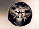
The flowmeter consisted of a rotor assembly that sensed the oxidizer flow, flow straighteners which directed LOX flow across the rotor, and two pickup coils located 180° apart, each with an electrical receptacle. As the LOX flow spun the turbine, the rotational rate was detected by the coils.
Here is a cut-away diagram of the LOX flowmeter:

Click image for a 29772691 pixel version of this image in a new window.
From page 1-42 of the F-1 Engine Familiarization Training Manual,
located in the archives of the U.S.
Space & Rocket Center. Also available from University
of Alabama at Huntsville's USSRC Archive [direct link to 16.8M PDF
file].
Scan and cleanup by heroicrelics.
Although the description from F-1 Familiarization referenced the "magnetic pickup that the flux density through the coil changes" and that the "flux lines through the coil build up and collapse", this description was not sufficiently clear so that I could understand method of measuring the rotation of the impeller.
However, the description of one of the patents stamped on the flowmeter, although describing a different part of the flowmeter, proved much more enlightening:
The speed of rotation of the rotor and thus the rate of flow of the fluid through the conduit can be measured by well-known electrical means comprising . . . a ring magnet mounted within the body portion of the rotor. Such magnet is in electrical cooperation by magnetic coupling with a coil which in turn is electrically connected to an electrical tachometer or frequency meter. An alternating current thus can be generated in the coil, the frequency of which is a direct function of the r.p.m. of the rotor, such frequency being measurable . . . and indicated as a rate of flow.
The flowmeter, then, is basically an alternator.
The patent application is accompanied by a diagram of a typical Pottermeter flowmeter, showing the magnet within the rotor and the pickup coil:

Click image for a 1754x1284 pixel version of this image in a new window.
Adapted from Figure 1 of US patent 2709755.
Cleanup and adaptation by heroicrelics.
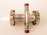
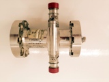
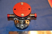
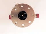
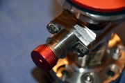
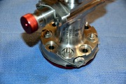
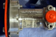
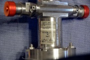
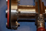
I've been contacted by two collectors whose collections include a LOX flowmeter, and they have provided the following photos. I've commingled the photos from the two collectors to provide a more comprehensive overview of this artifact.
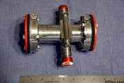 dsc_0842.jpg |
 flowmeter-1.jpg |
 flowmeter-2.jpg |
 dsc_0859.jpg |
 flowmeter-3.jpg |
 flowmeter-4.jpg |
 dsc_0856.jpg |
 dsc_0854.jpg |
 dsc_0846.jpg |
 dsc_0843.jpg |
 dsc_0857.jpg |